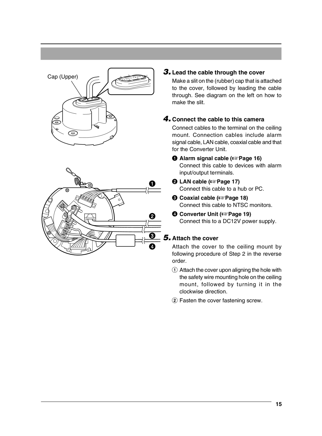
3. Lead the cable through the cover
Cap (Upper) | Make a slit on the (rubber) cap that is attached | |
| ||
| to the cover, followed by leading the cable | |
| through. See diagram on the left on how to | |
| make the slit. | |
| 4. Connect the cable to this camera | |
| Connect cables to the terminal on the ceiling | |
| mount. Connection cables include alarm | |
| signal cable, LAN cable, coaxial cable and that | |
| for the Converter Unit. | |
| 1 Alarm signal cable (☞Page 16) | |
| Connect this cable to devices with alarm | |
| input/output terminals. | |
1 | 2 LAN cable (☞Page 17) | |
Connect this cable to a hub or PC. | ||
|
| 3 Coaxial cable (☞Page 18) | |
| Connect this cable to NTSC monitors. | |
2 | 4 Converter Unit (☞Page 19) | |
Connect this to a DC12V power supply. | ||
| ||
3 | 5. Attach the cover | |
4 | Attach the cover to the ceiling mount by | |
| following procedure of Step 2 in the reverse | |
| order. |
1 Attach the cover upon aligning the hole with the safety wire mounting hole on the ceiling mount, followed by turning it in the clockwise direction.
2 Fasten the cover fastening screw.
15