3
General Information
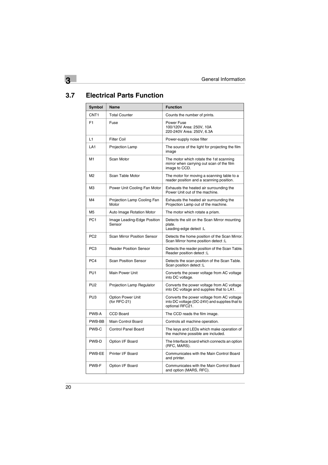
3.7Electrical Parts Function
Symbol | Name | Function |
CNT1 | Total Counter | Counts the number of prints. |
|
|
|
F1 | Fuse | Power Fuse |
|
| 100/120V Area: 250V, 10A |
|
| |
|
|
|
L1 | Filter Coil | |
|
|
|
LA1 | Projection Lamp | The source of the light for projecting the film |
|
| image |
|
|
|
M1 | Scan Motor | The motor which rotate the 1st scanning |
|
| mirror when carrying out scan of the film |
|
| image to CCD. |
|
|
|
M2 | Scan Table Motor | The motor for moving a scanning table to a |
|
| reader position and a scanning position. |
|
|
|
M3 | Power Unit Cooling Fan Motor | Exhausts the heated air surrounding the |
|
| Power Unit out of the machine. |
|
|
|
M4 | Projection Lamp Cooling Fan | Exhausts the heated air surrounding the |
| Motor | Projection Lamp out of the machine. |
|
|
|
M5 | Auto Image Rotation Motor | The motor which rotate a prism. |
|
|
|
PC1 | Image | Detects the slit on the Scan Mirror mounting |
| Sensor | plate. |
|
| |
|
|
|
PC2 | Scan Mirror Position Sensor | Detects the home position of the Scan Mirror. |
|
| Scan Mirror home position detect :L |
|
|
|
PC3 | Reader Position Sensor | Detects the reader position of the Scan Table. |
|
| Reader position detect :L |
|
|
|
PC4 | Scan Position Sensor | Detects the scan position of the Scan Table. |
|
| Scan position detect :L |
|
|
|
PU1 | Main Power Unit | Converts the power voltage from AC voltage |
|
| into DC voltage. |
|
|
|
PU2 | Projection Lamp Regulator | Converts the power voltage from AC voltage |
|
| into DC voltage and supplies that to LA1. |
|
|
|
PU3 | Option Power Unit | Converts the power voltage from AC voltage |
| (for | into DC voltage |
|
| optional RFC21. |
|
|
|
CCD Board | The CCD reads the film image. | |
|
|
|
Main Control Board | Controls all machine operation. | |
|
|
|
Control Panel Board | The keys and LEDs which make operation of | |
|
| the machine possible are included. |
|
|
|
Option I/F Board | The Interface board which connects an option | |
|
| (RFC, MARS). |
|
|
|
Printer I/F Board | Communicates with the Main Control Board | |
|
| and printer. |
|
|
|
Option I/F Board | Communicates with the Main Control Board | |
|
| and option (MARS, RFC). |
|
|
|
20