General Information
3
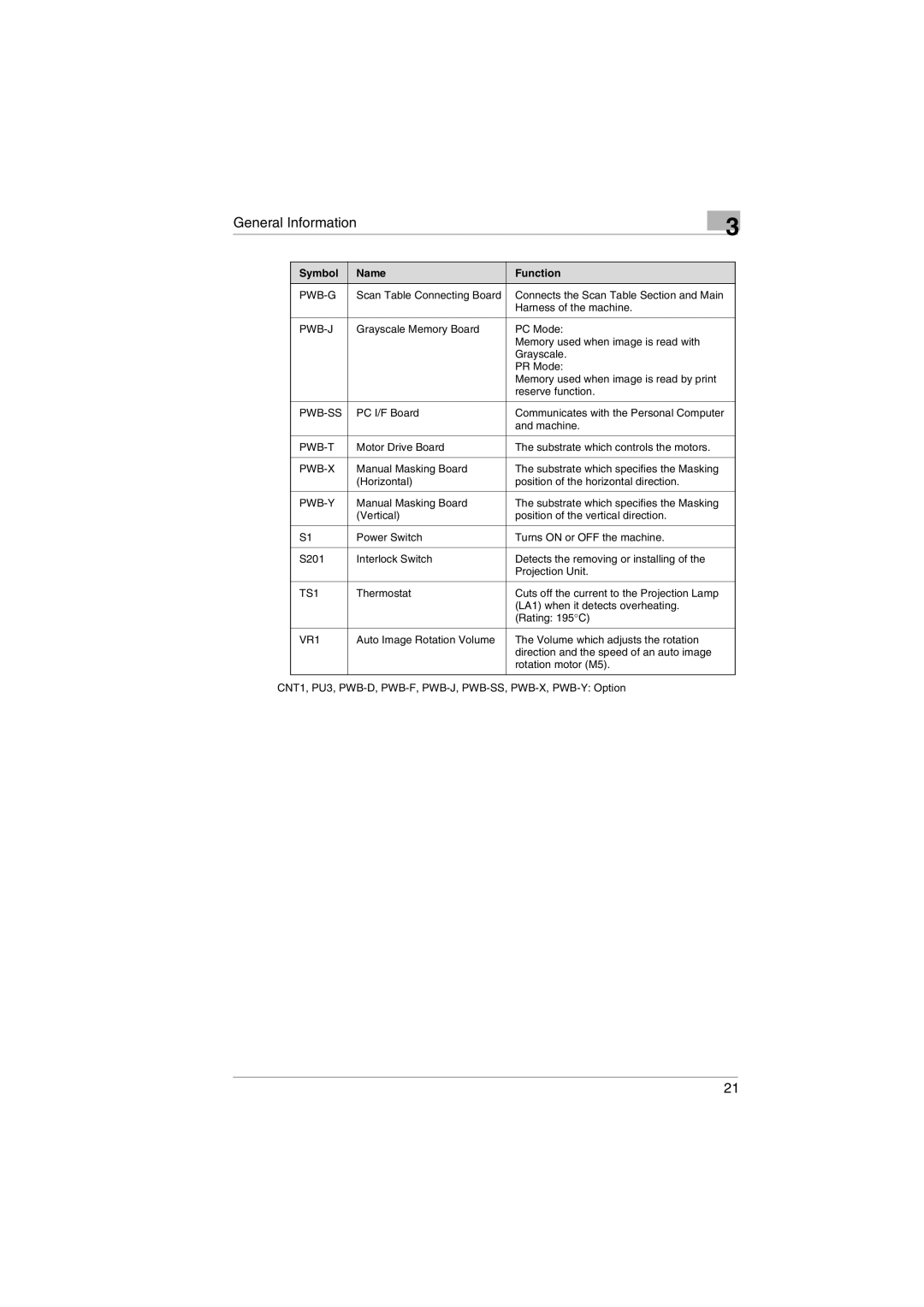
Symbol | Name | Function |
Scan Table Connecting Board | Connects the Scan Table Section and Main | |
|
| Harness of the machine. |
|
|
|
Grayscale Memory Board | PC Mode: | |
|
| Memory used when image is read with |
|
| Grayscale. |
|
| PR Mode: |
|
| Memory used when image is read by print |
|
| reserve function. |
|
|
|
PC I/F Board | Communicates with the Personal Computer | |
|
| and machine. |
|
|
|
Motor Drive Board | The substrate which controls the motors. | |
|
|
|
Manual Masking Board | The substrate which specifies the Masking | |
| (Horizontal) | position of the horizontal direction. |
|
|
|
Manual Masking Board | The substrate which specifies the Masking | |
| (Vertical) | position of the vertical direction. |
|
|
|
S1 | Power Switch | Turns ON or OFF the machine. |
|
|
|
S201 | Interlock Switch | Detects the removing or installing of the |
|
| Projection Unit. |
|
|
|
TS1 | Thermostat | Cuts off the current to the Projection Lamp |
|
| (LA1) when it detects overheating. |
|
| (Rating: 195°C) |
|
|
|
VR1 | Auto Image Rotation Volume | The Volume which adjusts the rotation |
|
| direction and the speed of an auto image |
|
| rotation motor (M5). |
|
|
|
CNT1, PU3,
21
