Machine Tyeps: 4215, 4219, 4220, 4221, and
Hardware Maintenance Manual
Page
Machine Tyeps: 4215, 4219, 4220, 4221, and
Hardware Maintenance Manual
Fourth Edition Octorber Copyright Lenovo 2010,
Contents
Appendix A. Notices
Chapter 11. Additional service
Chapter 10. FRU lists
information
Chapter 1. About this manual
Important Safety Information
Products marketed after June
Replacement FRU
Replacement FRU
Products marketed before June
General safety
Chapter 2. Safety information
Electrical safety
•Disconnect all power before
Safety inspection guide
Voltage-selectionswitch
Handling electrostatic discharge-sensitivedevices
Safety notices multi-lingualtranslations
Grounding requirements
DANGER
DANGER
Chapter 2. Safety information
≥55 kg 121.2 lbs
PERIGO
≥18 kg 37 lbs
≥32 kg 70.5 lbs
PRECAUCIÓN
CUIDADO
12Hardware Maintenance Manual
Chapter 2. Safety information
14Hardware Maintenance Manual
Chapter 2. Safety information
Pour éviter tout risque de choc électrique
•la jeter à leau
Soulevez la machine avec précaution
ACHTUNG
ACHTUNG
Chapter 2. Safety information
PERICOLO
ATTENZIONE
PERICOLO
Chapter 2. Safety information
PELIGRO
No debe
PRECAUCIÓN
PRECAUCIÓN
Lenovo Welcome
Chapter 3. General information
Online Books folder
Lenovo ThinkVantage Tools
Environment
Specifications
Dimensions
Weight
Chapter 4. General Checkout
Problem determination tips
–Has this configuration ever worked?
Lenovo ThinkVantage Toolbox
Chapter 5. Diagnostics
Lenovo System Toolbox
Creating a diagnostic disc
PC-Doctorfor Rescue and Recovery
PC-Doctorfor DOS
Running tests
Navigating through the diagnostics programs
Test results
Quick and Full erase - hard disk drive
Viewing the test log
Chapter 5. Diagnostics
38Hardware Maintenance Manual
Using passwords
Chapter 6. Using the Setup Utility program
Starting the Setup Utility program
Viewing and changing settings
Setting, changing, and deleting a password
Power-OnPassword
Administrator Password
Hard Disk Password
Selecting a temporary startup device
Advanced settings
Exiting from the Setup Utility program
Selecting a startup device
42Hardware Maintenance Manual
Creating RAID volumes
Chapter 7. Configuring RAID
RAID Level
Deleting RAID volumes
Hard disk drive boot error
Chapter 8. Symptom-to-FRUIndex
Power Supply Problems
FRU/Action
Diagnostic error codes
Diagnostic Error Code
000-002-XXX BIOS Timeout
FRU/Action
Diagnostic Error Code
001-00X-XXX System Error
001-01X-XXX System Error
001-254-XXX 001-255-XXX 001-256-XXX
Diagnostic Error Code
001-260-XXX 001-264-XXX System IRQ error
FRU/Action
FRU/Action
Diagnostic Error Code
001-286-XXX 001-287-XXX 001-288-XXX System Timer
005-00X-XXX Video error
FRU/Action
Diagnostic Error Code
005-016-XXX Video Simple Pattern test failure
011-013-XXX 011-014-XXX Serial port Control
Diagnostic Error Code
005-2XX-XXX 005-3XX-XXX Video subsystem error
FRU/Action
014-03X-XXX 014-04X-XXX Parallel port failure
Diagnostic Error Code
FRU/Action
014-013-XXX 014-014-XXX Parallel port Control
FRU/Action
Diagnostic Error Code
014-2XX-XXX 014-3XX-XXX Parallel port failure
FRU/Action
Diagnostic Error Code
1. Press F3 to review the log file
FRU/Action
Diagnostic Error Code
025-00X-XXX 025-01X-XXX IDE interface failure
025-02X-XXX 025-03X-XXX 025-04X-XXX IDE Interface
Diagnostic Error Code
030-03X-XXX 030-04X-XXX SCSI interface error
FRU/Action
FRU/Action
Diagnostic Error Code
Press F3 to review the log file
FRU/Action
Diagnostic Error Code
FRU/Action
Diagnostic Error Code
080-197-XXX Game Port interface test warning
1. See “Undetermined problems” on page
Diagnostic Error Code
FRU/Action
1. See “Undetermined problems” on page
Diagnostic Error Code
FRU/Action
302-XXX-XXX Mouse error
Diagnostic Error Code
FRU/Action
Beep Symptom
Beep symptoms
Diagnostic Error Code
415-XXX-XXX Modem error
POST error codes
Description/Action
Miscellaneous error messages
POST Error Message
Message/Symptom
b. Second device - hard disk
Message/Symptom
FRU/Action
a. First device - network
Undetermined problems
68Hardware Maintenance Manual
Locations
Locating connectors on the front of your computer
Locating connectors on the rear of your computer
Chapter 9. Replacing FRUs
Figure 2. Rear connector locations
Locating components
Figure 3. Component locations
Locating parts on the system board
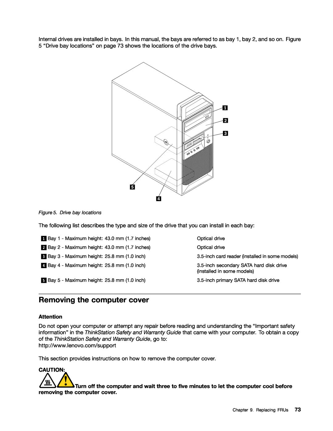
Locating internal drives
Removing the computer cover
Removing and reinstalling the front bezel
Installing or replacing a PCI card
Figure 8. Opening the PCI card latch
76Hardware Maintenance Manual
Figure 9. Removing a PCI card
Installing or replacing a memory module
5.Open the retaining clips
Installing or replacing the optical drive
Figure 14. Removing the optical drive
Figure 15. Installing the optical drive retainer
Replacing the power supply assembly
Replacing the battery
To replace the battery, do the following
Replacing the heat sink and fan assembly
Replacing the microprocessor
Notes
Replacing the system board
17.Go to “Completing the FRU replacement” on page
To install the microprocessor socket cover
Replacing the primary hard disk drive
92Hardware Maintenance Manual
Replacing the secondary hard disk drive
Figure 29. Removing the secondary hard disk drive
94Hardware Maintenance Manual
Replacing the card reader
Replacing the front fan assembly
Figure 34. Removing the front fan assembly
Replacing the rear fan assembly
Figure 36. Removing the rear fan assembly
Replacing the front audio and USB assembly
Replacing the internal speaker
and push downward on the internal speaker
Figure 40. Installing a new internal speaker
Completing the FRU replacement
104Hardware Maintenance Manual
Figure 41. Reinstalling the computer cover
Overall: MT 4215, 4219, 4220, 4221, and
Chapter 10. FRU lists
MT 4221: CTO
Item #
FRUs
FRU #
MT 4215: CTO
Item #
FRUs
FRU #
Microprocessor, Clarkdale - Core i5-670 /3.46GHz
Item #
FRUs
FRU #
Memory module, DDR3 ECC PC3-106002GB UDIMM
Item #
FRUs
FRU #
Memory module, DDR3 non-ECC PC3-106002GB UDIMM
Item #
FRUs
FRU #
Optical drive, Blu-RayDVD Burner SATA
Item #
FRUs
FRU #
MT 4215: CTO
Item #
FRUs
FRU #
95U 95F 96U 96F 97U 97F A2G A3G A4M A8C
Item #
FRUs
FRU #
MT 4215 CTO
Item #
FRUs
FRU #
A4M A5M A6J A7J A8C
Item #
FRUs
FRU #
FRU #
Mechanical FRUs
Item #
FRUs
FRU #
FRUs
FRU, speaker cable_R_9*5_400mm
FRUs
FRU, Intrusion switch assembly
FRU #
FRU #
FRUs
FRU, PS2 cable_R_170mm_knock out with screw
Keyboard Lenovo Preferred Pro USB --without hub
Keyboard and Mouse
FRU #
FRU #
Keyboard Lenovo Preferred Pro USB --without hub
Belgium English
FRU #
Keyboard Lenovo Preferred Pro USB --without hub
Dutch
FRU #
Keyboard Lenovo Preferred Pro USB --without hub
Greek/US
FRU #
Keyboard Lenovo Preferred Pro USB --without hub
Korean
FRU #
Keyboard Lenovo Preferred Pro USB --without hub
Romanian
FRU #
Keyboard Lenovo Preferred Pro USB --without hub
SF/G
FRU #
Keyboard Lenovo Preferred Pro USB --without hub
FRU #
Keyboard Preferred Pro Full Size PS/2
FRU #
Keyboard Preferred Pro Full Size PS/2
PS/2--BelgiumEnglish
FRU #
Keyboard Preferred Pro Full Size PS/2
PS/2--Dutch
FRU #
Keyboard Preferred Pro Full Size PS/2
PS/2--Greek/US
FRU #
Keyboard Preferred Pro Full Size PS/2
PS/2--Korean
FRU #
Keyboard Preferred Pro Full Size PS/2
PS/2--Russian/Cyrillic
FRU #
Keyboard Preferred Pro Full Size PS/2
PS/2--Thailand
FRU #
Keyboard Enhanced Performance
FRU #
Keyboard Enhanced Performance
Enhanced--Bulgarian
FRU #
Keyboard Enhanced Performance
Enhanced--FrenchCanadian
FRU #
Keyboard Enhanced Performance
Enhanced--Hungarian
FRU #
Keyboard Enhanced Performance
Enhanced--Norwegian
FRU #
Keyboard Enhanced Performance
Enhanced--Slovak
FRU #
Keyboard Enhanced Performance
FRU #
Mice
Adapters and miscellaneous FRUs
Adapters and miscellaneous FRUs
Mice
FRU #
FRU #
Adapters and miscellaneous FRUs
MT 4219: CTO
FRU #
Adapters and miscellaneous FRUs
DVI to VGA Dongle
Power Cords --primary
Power Cords
FRU #
FRU #
Power Cords --primary
Line Cord-Australia /New Zealand
FRU #
Power Cords --primary
Line Cord - A models
FRU #
Power Cords --primary
Power Cords --secondary
FRU #
FRU #
Power Cords --secondary
Line Cord - Brazil
FRU #
Power Cords --secondary
41R3233
FRU #
Recovery discs
Windows Vista Business 32 Recovery CD
Power Cords --secondary
Windows 7 Professional
Windows 7 Professional 64 Recovery CD
FRU #
FRU #
Windows 7 Professional
Czech
FRU #
Windows 7 Professional
Greek
FRU #
Windows 7 Professional
Sebian- Latin
FRU #
Windows 7 Professional
Traditional Chinese
FRU #
Windows 7 Professional 64 Office 2010 Starter
FRU #
Windows 7 Professional 64 Office 2010 Starter
03W2742
FRU #
Windows 7 Professional 64 Office 2010 Starter
Hungarian
FRU #
Windows 7 Professional 64 Office 2010 Starter
Romanian
FRU #
Windows 7 Professional 64 Office 2010 Starter
Simplified Chinese
FRU #
Windows XP Professional 64 Recovery CD
Windows XP Professional 64 Mono Recovery CD
Windows 7 Professional 64 Office 2010 Starter
FRU #
Windows XP Professional Recovery CD
162Hardware Maintenance Manual
Windows XP Professional
FRU #
Windows XP Professional
Multilingual Nordics: DK/FI/SV/NO/EN
164Hardware Maintenance Manual
Operating system password
Chapter 11. Additional service information
Security features
Hardware-controlledpasswords
b.Click Downloads and drivers
Updating flashing the BIOS from a disc
Updating flashing BIOS from your operating system
Recovering from a POST/BIOS update failure
Automatic Power-Onfeatures
Power management
168Hardware Maintenance Manual
U.S.A Attention Lenovo Director of Licensing
Appendix A. Notices
Lenovo United States, Inc
1009 Think Place - Building One Morrisville, NC
Trademarks
Television output notice
Page
Part Number: 71Y8031 Printed in USA
71Y8031
1P P/N: 71Y8031