ThinkServer TD230 Hardware Maintenance Manual
Page
ThinkServer TD230 Hardware Maintenance Manual
Eighth Edition October Copyright Lenovo 2010
Contents
Parts listing, TD230 Types 1027, 1029, 1039, 125
Safety information
About this manual
제품을 사용하기 전에 제품과 함께 제공되는 문서 DVD의 다국어 안전 지침을 주의 깊게 읽어보십시오
在使用本产品之前,请务必先阅读和了解产品附带的文档 DVD 中的多语言安全说明。
使用本產品之前,請務必閱讀並瞭解產品隨附的文件 DVD 上的多國語言版本安全資訊。
Statement
ThinkServer TD230 Hardware Maintenance Manual
≥ 18 kg 39.7 lb ≥ 32 kg 70.5 lb ≥ 55 kg 121.2 lb
ThinkServer TD230 Hardware Maintenance Manual
About this manual
Important information about replacing RoHS compliant FRUs
About this manual
ThinkServer TD230 Hardware Maintenance Manual
Features and specifications
General information
Reliability, availability, and serviceability
Software programs
EasyStartup
EasyManage
General information
ThinkServer TD230 Hardware Maintenance Manual
Troubleshooting tables
DVD drive problems
General problems
Hard disk drive problems
Intermittent problems
Keyboard, mouse, or pointing-device problems
Memory problems
Microprocessor problems
Monitor problems
Optional-device problems
Power problems
Serial port problems
Software problems
Universal Serial Bus USB port problems
Solving power problems
Solving Ethernet controller problems
Solving undetermined problems
Diagnostic programs and messages
Event logs
System event log
Diagnostic LEDs on the front panel and the system board
Locating parts, controls, LEDs, and connectors
Front view
Opening the front door
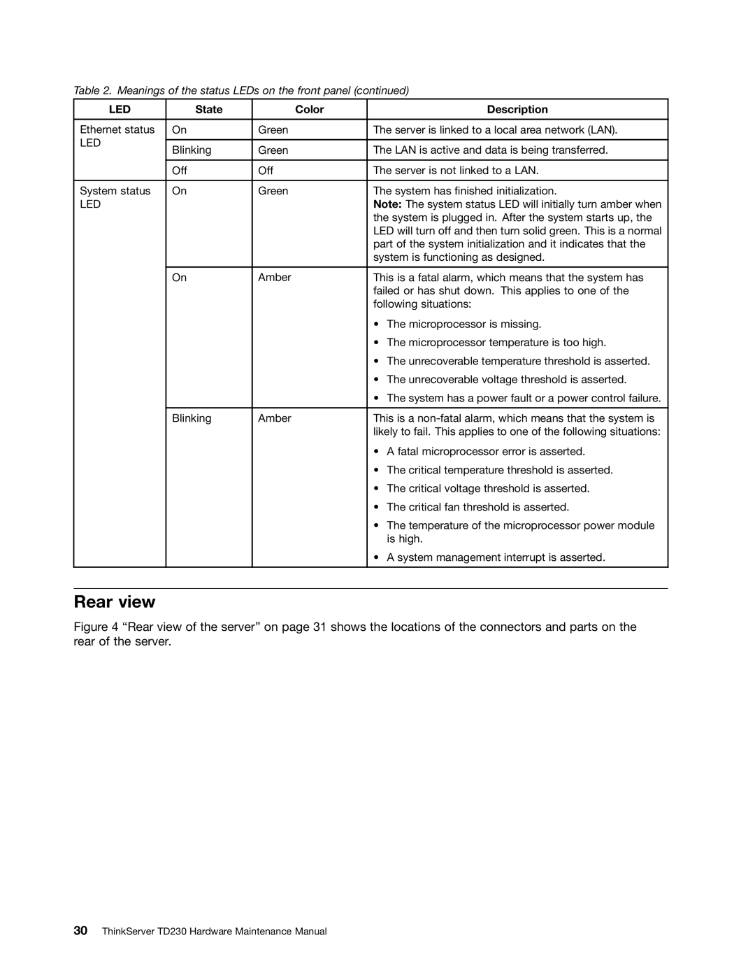
LED
Rear view
LED
Hot-swap hard disk drive status LEDs
Rear view of the server
LEDs for the Ethernet connectors
Locating server components
Locating parts on the system board
Locating major parts on the system board
Locating diagnostic LEDs on the system board
Jumper block settings
Jumper Block Pin position Description
Locating parts, controls, LEDs, and connectors
ThinkServer TD230 Hardware Maintenance Manual
Guidelines
Basic guidelines
System reliability guidelines
Handling static-sensitive devices
Working inside the server with the power on
Guidelines for trained service technicians
Inspecting for unsafe conditions
Guidelines for servicing electrical equipment
Removing the server cover
Sliding the server cover to the rear
Removing and reinstalling the front bezel
Removing the server cover
Locking or unlocking the hard disk drive side door
Removing the front bezel
Opening the side door
Locking the side door
Installing or removing a memory module
Memory module installation rules
Installing a memory module
Removing a memory module
Opening the retaining clips of the memory slot
Removing or installing internal drives
Removing the memory module
Removing the optical drive
Removing the optical drive
Installing the optical drive
Removing the optical drive retainers
Installing the optical drive retainers
Installing the optical drive
Removing a hot-swap hard disk drive
Opening the handle of the hot-swap hard disk drive bracket
Replacing FRUs
Installing a hot-swap hard disk drive
Removing the hot-swap hard disk drive
Press the blue button To open the side door
Opening the handle of the hot-swap hard disk drive bracket
Removing the hot-swap hard disk drive bracket
Installing the hard disk drive into the bracket
Removing a non-hot-swap hard disk drive
Locking the hot-swap hard disk drive in the drive bay
Opening the side door
Replacing FRUs
Installing a non-hot-swap hard disk drive
Removing the screws that secure the hard disk drive
Opening the side door
Sliding the non-hot-swap hard disk drive bracket out
Securing the hard disk drive in the bracket by screws
Installing or removing a PCI card
Sliding the non-hot-swap hard disk drive into the bay
Installing a PCI card
Installing a PCI card
Removing a PCI card
Installing or removing the Ethernet card
Installing the Ethernet card
Removing the Ethernet card
Installing the RAID 5 key
Removing the RAID 5 key
What to do next
Installing the TR 500 key
Removing the RAID 5 key
Installing the TR 500 key
Removing the TR 500 key
Removing the TR 500 key
Installing the RMM3
About the RMM3
Removing the PCI card slot bracket for the RMM3 connector
Installing the RMM3 on the slot bracket
Installing the slot bracket with RMM3
Connecting the ribbon cable
Removing the RMM3
Replacing FRUs
Installing, removing, or replacing hardware devices
Removing or installing the RAID card
Removing the RAID card
Installing the RAID card
Installing the ThinkServer RAID 500 Adapter
Installing the ThinkServer 8708EM2 RAID Adapter
Connecting the mini SAS signal cables
Connecting the mini SAS signal cables
Installing the ThinkServer 8708EM2 RAID Battery
Top view of the battery card assembly
Connecting the mini SAS cable
Installing the battery card assembly onto the RAID card
SAS connectors on the hot-swap hard disk drive backplanes
Removing or installing the heat sink and fan assembly
Removing the heat sink and fan assembly
Replacing FRUs
Heat sink and fan assembly
Installing the heat sink and fan assembly
Heat sink and fan assembly
Removing or installing a front fan
Removing a front fan
ThinkServer TD230 Hardware Maintenance Manual
Installing a front fan
Removing the front fan
ThinkServer TD230 Hardware Maintenance Manual
Removing or installing the rear fan
Installing the front fan
Removing the rear fan
Installing the rear fan
Removing the rear fan
ThinkServer TD230 Hardware Maintenance Manual
Removing or installing the microprocessor
Installing the rear fan
Removing the microprocessor
Removing the microprocessor
Installing the microprocessor
Lifting the handle
Opening the retainer
Replacing the system board battery
Installing the microprocessor
Removing or installing the system board
Removing the system board
Heat to more than 100 C 212 F Repair or disassemble
Removing the eight screws that secure the system board
ThinkServer TD230 Hardware Maintenance Manual
Installing the system board
Installing the eight screws that secure the system board
Replacing the power supply assembly
Removing the screws and the metal clip
Removing the power supply assembly
Installing the power supply assembly
Completing the parts replacement
Installing the server cover
Connecting the cables
Updating the server configuration
Turning on the server
Connecting external devices
Turning off the server
Replaceable server components
125
Index Description CRU part FRU part Number Tier
Parts listing, TD230 Types 1027, 1029, 1039, and 1040
Index Description CRU part FRU part Number Tier
Index Description CRU part FRU part Number Tier
Index Description CRU part FRU part Number Tier
CTO
Memory module, 4 GB DDR3 Rdimm 1333 MHz models 46U3443
Index Description CRU part FRU part Number Tier
Index Description CRU part FRU part Number Tier
Windows 2008 SBS SP2 STD 64 bit United Sates models 90Y1174
Index Description CRU part FRU part Number Tier
Index Description CRU part FRU part Number Tier
Power cords
Power cords, Type
Power cords, Type
41R3278 Taiwan models CTO 43N9029 Thailand models CTO
ThinkServer TD230 Hardware Maintenance Manual
Using the Setup Utility program
Setup Utility program
Ethernet controller configuration
ThinkServer RAID 500 Adapter Configuration Utility program
Starting the Setup Utility program
Introduction of the Bios items
Performance Configuration on
Submenus under the Memory RAS and Performance
Submenus under the Serial Port Configuration
Submenus under the PCI Configuration
Using passwords
Exiting the Setup Utility program
Set Administrator Password Set User Password
Password considerations
Setting, changing, or deleting a password
RAID controllers
Using the ThinkServer EasyStartup program
Intel ESRT2 Sata
Setup and configuration
Before you use the EasyStartup DVD
Configuring RAID
Typical operating system installation
Configuring the onboard Sata software RAID
RAID information
Creating a RAID volume
Select Easy Configuration
Online
Degrade
Initializing the RAID volume
Deleting the RAID volume
Select Clear Configuration
Rebuilding the RAID volume
Checking the RAID 1 volume consistency
Connecting the Sata cables
Configuring the Gigabit Ethernet controller
Using the EasyUpdate Firmware Updater program
Installing the ThinkServer EasyManage program
Updating the firmware
Configuring the server
ThinkServer TD230 Hardware Maintenance Manual
Specifications
Battery life and data retention time
161
ThinkServer TD230 Hardware Maintenance Manual
Before you call
163
Using other services
Purchasing additional services
ThinkServer TD230 Hardware Maintenance Manual
Appendix C. Notices
167
Trademarks
Important notes
Product recycling and disposal
Particulate contamination
Battery return program
Contaminant Limits
US & Canada Only
For the European Union
German Ordinance for Work gloss statement
Industry Canada Class a emission compliance statement
For California
Appendix C. Notices
ThinkServer TD230 Hardware Maintenance Manual
Index
175
RMM3
177
USB
Page
Part Number 1P P/N