4026-0XX
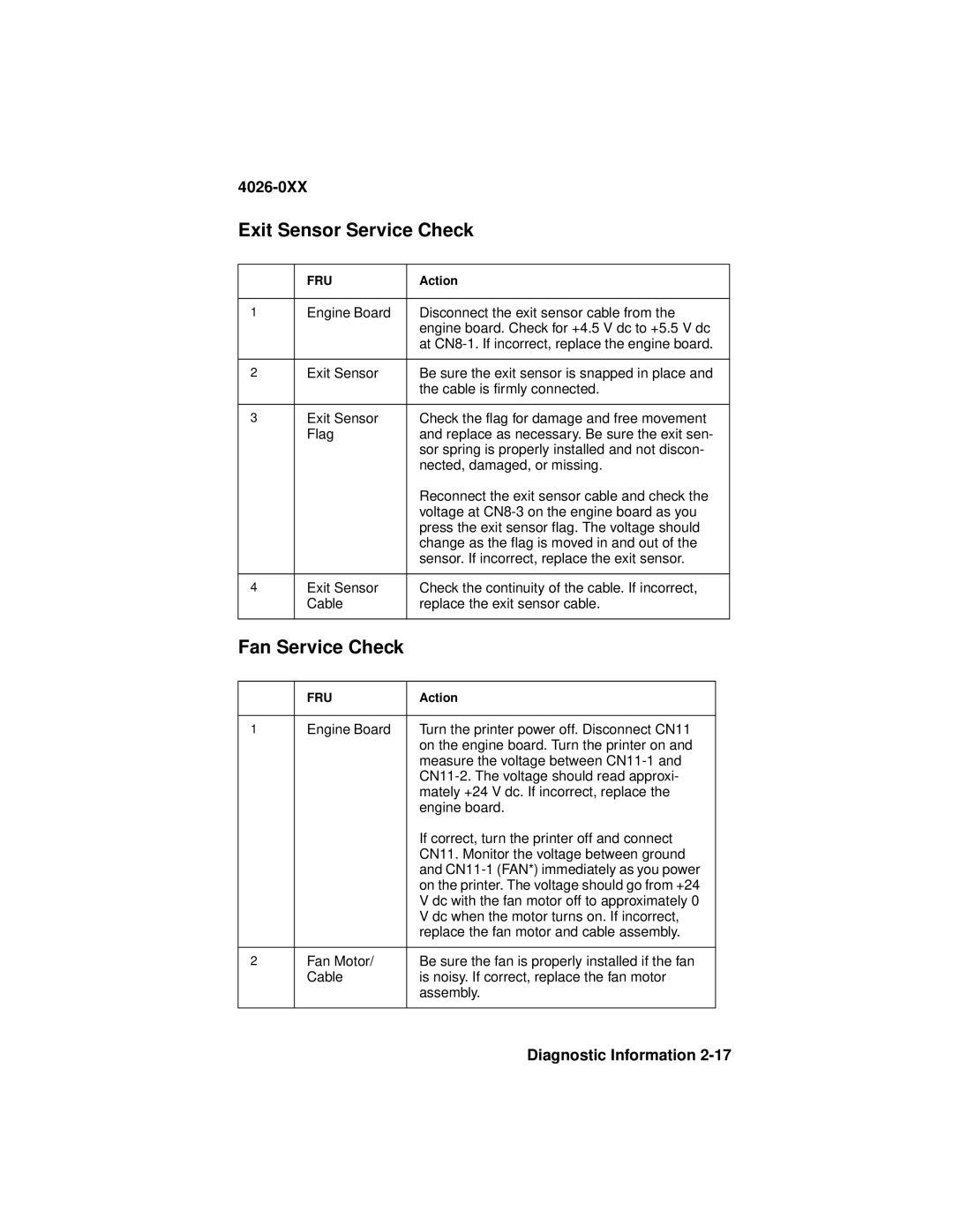
Exit Sensor Service Check
| FRU | Action | |
|
|
|
|
1 | Engine Board | Disconnect the exit sensor cable from the | |
|
| engine board. Check for +4.5 V dc to +5.5 V dc | |
|
| at | |
|
|
|
|
2 | Exit Sensor | Be sure the exit sensor is snapped in place and | |
|
| the cable is firmly connected. | |
|
|
|
|
3 | Exit Sensor | Check the flag for damage and free movement | |
| Flag | and replace as necessary. Be sure the exit sen- | |
|
| sor spring is properly installed and not discon- | |
|
| nected, damaged, or missing. | |
|
| Reconnect the exit sensor cable and check the | |
|
| voltage at | |
|
| press the exit sensor flag. The voltage should | |
|
| change as the flag is moved in and out of the | |
|
| sensor. If incorrect, replace the exit sensor. | |
|
|
|
|
4 | Exit Sensor | Check the continuity of the cable. If incorrect, | |
| Cable | replace the exit sensor cable. | |
|
|
|
|
Fan Service Check |
|
| |
|
|
|
|
| FRU | Action |
|
|
|
|
|
1 | Engine Board | Turn the printer power off. Disconnect CN11 |
|
|
| on the engine board. Turn the printer on and |
|
|
| measure the voltage between |
|
|
|
| |
|
| mately +24 V dc. If incorrect, replace the |
|
|
| engine board. |
|
|
| If correct, turn the printer off and connect |
|
|
| CN11. Monitor the voltage between ground |
|
|
| and |
|
|
| on the printer. The voltage should go from +24 |
|
|
| V dc with the fan motor off to approximately 0 |
|
|
| V dc when the motor turns on. If incorrect, |
|
|
| replace the fan motor and cable assembly. |
|
|
|
|
|
2 | Fan Motor/ | Be sure the fan is properly installed if the fan |
|
| Cable | is noisy. If correct, replace the fan motor |
|
|
| assembly. |
|
|
|
|
|