Touch Screen Display
Configuring the Input Contact Isolator Settings
The Input Contact Isolator (ICI) is an optional,
The contact is set to either be normally open or normally closed. When a contact closes or opens, an event is triggered. See 6.2 - Input Contact Isolator Board for more information on the ICI.
The Input Contact Isolator options are configured through the Input Contact Isolator dialog box, which is accessed from the Comm Options dialog box. The Input Contact Isolator dialog box contains eight choices to match the eight channel input board. You can label each button to identify the event associated with the contact. When the dialog box is accessed, each button flashes to display the Input Contact Isolator number and the user entered label. This label also appears in the Display Panel when an event related to an Input Isolator Connector is triggered.
The Input Contact Isolator dialog box allows you to:
•Label the input contact assignments for your setup.
•Set the delay for an external event triggering an alarm.
•Review the isolator contact assignments, once the labels are entered.
The delay allows you to set the number of seconds which a condition needs to persist to trigger an alarm.
These input alarms can also be configured to activate a programmable relay output, which is dis- cussed in Configuring the Programmable Relay Board Settings on page 109.
To configure the Input Contact Isolator relays:
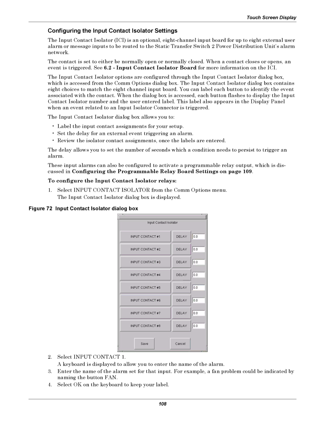
1.Select INPUT CONTACT ISOLATOR from the Comm Options menu. The Input Contact Isolator dialog box is displayed.
Figure 72 Input Contact Isolator dialog box
2.Select INPUT CONTACT 1.
A keyboard is displayed to allow you to enter the name of the alarm.
3.Enter the name of the alarm set for that input. For example, a fan problem could be indicated by naming the button FAN.
4.Select OK on the keyboard to keep your label.
108