Power Distribution
STS2/PDU
Contacting Liebert for Support
Table of Contents
Theory of Operation
Alarms and Faults
Introduction to STS2/PDU Operations
Operating Instructions
Touch Screen Display
Specifications
Communication Interfaces
Event Message Help Text Maintenance
Customer Settings
Page
Tables
Important Safety Instructions
Page
Unpacking and Inspections
External Inspections
Unloading and Handling
Internal Inspections
Shipping weights typical
Model Weight lbs. kg
Handling Considerations
Operating Environment
Recommended Minimum Service Clearances
Heat Output
Location Considerations
Feet = Meters
Altitude
Altitude conversion-feet to meters
Locating the STS2/PDU
Anchoring the Unit to the Floor
Leveling of the 250A Only STS2/PDU Without Anchoring
Input and Output Power Connections
Power and Control Wiring
Typical STS2/PDU, one-line diagram
Input/output conduit plate specifications
Rating Maximum Number Conduits Size,
System Grounding
Control Wiring Connections
Remote Source Selection Wiring
Remote source selection terminal block
Power Supply
Terminal block 1 and terminal block 2 wire connections
Customer Connections
Output Power Wiring
Distribution configurations
Output Breaker
Options
Programmable Relay Board
Input Contact Isolator Board
Programmable relay board pinout Channel Pin No
Network Interface Card NIC
Comms Board
Internal Modem
Remote Source Selection
Key Lockout Switch
Static Switch Redundant Output Breaker
Inline Panelboards
Installation Drawings
Outline drawing, 250A STS2/PDU
Installation Drawings
Installation Drawings
Installation Drawings
Installation Drawings
Installation Drawings
Installation Drawings
Installation Drawings
Installation Drawings
Installation Drawings
Installation Drawings
Installation Drawings
Installation Drawings
Installation Drawings
Installation Drawings
Installation Drawings
Installation Drawings
Electrical field connections, 250A STS2/PDU input with CB3
Installation Drawings
Installation Drawings
Installation Drawings
Electrical field connections, 800A STS2/PDU input with CB3
Installation Drawings
Installation Drawings
Installation Drawings
Installation Drawings
Installation Drawings
Installation Drawings
Installation Drawings
Installation Drawings
Installation Drawings
Installation Drawings
Installation Drawings
Installation Drawings
Installation Drawings
Installation Drawings
Installation Drawings
Installation Drawings
Control wiring, 800A STS2/PDU, left side distribution
Control wiring, 800A STS2/PDU, right side distribution
Control connection location, 250A STS2/PDU
Control connection location, 400-800A STS2/PDU
Installation Drawings
Control wiring for the programmable relay board option
Control wiring for the input contact isolator board option
Control wiring for comms board
Control wiring for the internal modem option
Control wiring for the Network Interface Card NIC option
Control wiring for the RS-232 Port
Control wiring for remote source selection option
Color LCD touch screen display
Non-automatic breaker schedule, 250-800A
Input circuit breaker schedule, 250-800A
Output circuit breaker schedule, 250-800A
Circuit Breakers
Redundancy
System Description
Introduction to STS2/PDU Operations
Reliability and Agency Requirements
Factory Backup and Service Assistance
Modes of Operation
Normal Preferred Source
Transfer Inhibit
Operator Controls
Transfer
Bypass
General Description
Theory of Operation
Detailed Component Description
Circuit Breakers and Non-Automatic Circuit Breakers
Audible Alarm
Firmware
SCRs
Normal System Turn-On
Operating Instructions
Manual Transfer / Preferred Source Selection
Enabling Remote Source Selection
To manually select the preferred source
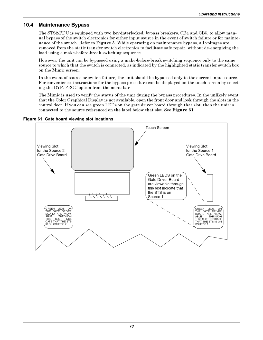
Maintenance Bypass
Gate board viewing slot locations
Bypass Procedures for Source
To return to the normal mode
Normal System Shutdown
Shutdown in Static Transfer Switch Mode
To return to normal mode
Shutdown in Maintenance Bypass Mode
Alarms and Faults
Event Mask
Event and History Logs
Event Log
History Log
Alarm Notes
List of Messages
Alarm Message Description/Cause Action
Event messages
Sources OUT of Sync
Communication Interfaces
Terminal commands
Using the RS-232 Port
Connecting and Using a Terminal
Keys Function
Item Parameter
Configuring the STS2/PDU via the Terminal
Groups Parameter
Type Definition
Value Parameter
Value types
Bitpacked Options With the Terminal
Group settings and values
Comms Options
Setting Bitpacked Options With the Terminal
Options1
Binary-hexadecimal conversions
Critical Option Enabling
Non-Critical Option Enab
Binary Hex Value Equivalent
Putting the Terminal Command Together
Setting Event Masks with the Terminal
Examples of Event Mask Settings
Display Overview
Touch Screen Display
Menu Overview
Backspace
To set or reset the password
Using the Optional Key Lockout Switch
Using the Password
Changes disabled Changes enabled
Event Controls
Configuration Menu
Mimic Display
Event Display
Event Masks
To set the event masks
Source Setpoints
User Settings
To access the User Settings dialog box
Setpoint parameters
To configure the setpoints for each source
Button Range Default Comments
103
Button Range Default Resolution
System Settings
To access the System Settings menu
PDU Setpoints
Option buttons
Configuring the Modem
Comm Options
To configure the modem
Modem dialog box
107
Configuring the Input Contact Isolator Settings
To configure the Input Contact Isolator relays
Relay Setting Definition
Configuring the Programmable Relay Board Settings
Standard settings for programmable relays
Configuring the Network Interface Card
If the optional OpenComms NIC is installed in the STS2/PDU
System Options
SiteScan Configuration
Saving Your Communications Configurations
Dual Output Breaker
PDU
Logs
To use the Event Log
Cleaning the LCD Touch Screen
System Configuration
Specifications
Surge Suppression
System Components
Electrical Requirements
Response Time
Cooling
Frame and Enclosure
Caster and Leveling 250A only
Frame sizes
Cable Entrance
Access
Circuit Breakers
Doors
Terminal Port Connections
Pin Signal Name Function / Comments
14.2.9 RS-232 Port
MTA plug pinout
14.2.11 RS-232 Interface Parameters
Maintenance Bypass
See 10.4 Maintenance Bypass for instructions
Fuseless Design
Event Message Help Text
Key
122
PWR Sply S1 AC Fail
PWR Sply DC a Fail
PWR Sply DC B Fail
PWR Sply S2 AC Fail
OUT Volt Sense Fail
S1 SCR Sense Fail
S1 Volt Sense Fail
S2 Volt Sense Fail
S2 Curr Sense Fail
S2 SCR Sense Fail
S1 Curr Sense Fail
Internal Comm Fail
CB1 Shunt Trip Fail
Input 2 Surge Failure
CB2 Shunt Trip Fail
Input 1 Surge Failure
S1 UV RMS
Heat Sink Overtemp
S1 UV
S1 Fail
S1 OV
S1 OF/UF
S2 UV
S2 UV RMS
S2 UF/OF
S2 Fail
S1 I-PEAK
Load on ALT Source
CB1 S1 Open
CB5 S1 BYP Closed
CB2 S2 Open
CB4 S1 BYP Closed
CB3 Output Open
CB3A Output Open
Transfer Inhibited
Input 1 Overvoltage
Output UV
History LOG Frozen
Input 1 Undervoltage
Load Overcurrent
Input 2 Overvoltage
Input 2 Undervoltage
Ground Overcurrent
Neutral Overcurrent
Load Voltage THD
Input 1 OF/UF
Input 2 OF/UF
141
142
Transfer Counter Cleared
Proper Tightening of Nuts and Bolts
Testing the STS2/PDU
Maintenance
Changing the Air Filter
Programmable relay board settings record
Programmable Relay Board Settings
Customer Settings
Channel PRB Notes
Input Contact Isolator Settings
Input contact isolator settings record
Page
Locations
Technical Support/Service
Company Behind the Products
Asia 23F, Allied Kajima Bldg