Options
6.0OPTIONS
This section discusses the options available for the STS2/PDU. The communications options are also discussed in 12.0 - Communication Interfaces.
! WARNING
All options must be installed by Liebert Global Services or Liebert
6.1Programmable Relay Board
The programmable relay board (PRB) provides a means to trigger an external device when an event occurs in the STS2/PDU. Each PRB has 8 channels. Each channel has two sets of
Any alarm or event may be programmed to any channel or channels. Up to ten (10) events may be programmed to a relay. If multiple events are grouped to one relay, group the events logically to sim- plify troubleshooting when an event is triggered. The same alarm or event may be programmed to more than one channel. Up to two programmable relay boards can be installed in the STS2/PDU for a total of 16 channels. Programming is performed through the touch screen display.
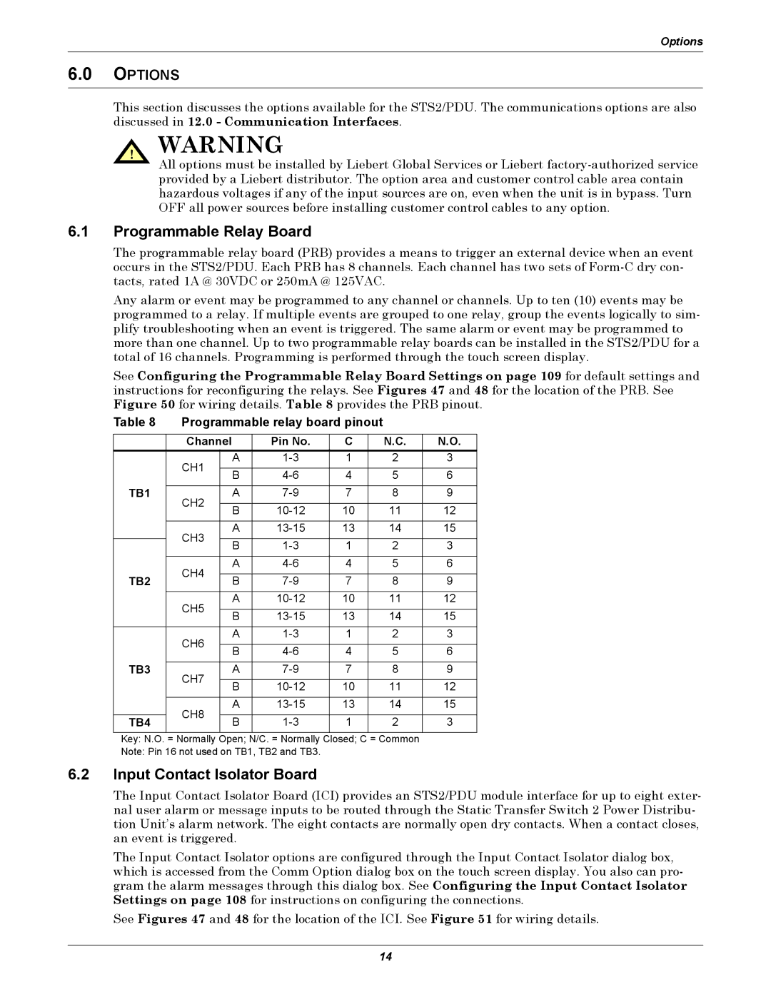
See Configuring the Programmable Relay Board Settings on page 109 for default settings and instructions for reconfiguring the relays. See Figures 47 and 48 for the location of the PRB. See Figure 50 for wiring details. Table 8 provides the PRB pinout.
Table 8 | Programmable relay board pinout |
|
| |||||
|
|
|
|
|
|
|
| |
| Channel |
| Pin No. | C |
| N.C. | N.O. | |
| CH1 |
| A | 1 |
| 2 | 3 | |
|
|
|
|
|
|
|
| |
|
| B | 4 |
| 5 | 6 | ||
|
|
|
| |||||
TB1 |
|
|
|
|
|
|
|
|
CH2 |
| A | 7 |
| 8 | 9 | ||
|
|
|
|
|
|
|
| |
|
| B | 10 |
| 11 | 12 | ||
|
|
|
| |||||
|
|
|
|
|
|
|
|
|
| CH3 |
| A | 13 |
| 14 | 15 | |
|
|
|
|
|
|
|
| |
|
| B | 1 |
| 2 | 3 | ||
|
|
|
| |||||
|
|
|
|
|
|
|
|
|
| CH4 |
| A | 4 |
| 5 | 6 | |
|
|
|
|
|
|
|
| |
TB2 |
| B | 7 |
| 8 | 9 | ||
|
|
| ||||||
| CH5 |
| A | 10 |
| 11 | 12 | |
|
|
|
|
|
|
|
| |
|
| B | 13 |
| 14 | 15 | ||
|
|
|
| |||||
|
|
|
|
|
|
|
|
|
| CH6 |
| A | 1 |
| 2 | 3 | |
|
|
|
|
|
|
|
| |
|
| B | 4 |
| 5 | 6 | ||
|
|
|
| |||||
TB3 |
|
|
|
|
|
|
|
|
CH7 |
| A | 7 |
| 8 | 9 | ||
|
|
|
|
|
|
|
| |
|
| B | 10 |
| 11 | 12 | ||
|
|
|
| |||||
|
|
|
|
|
|
|
|
|
| CH8 |
| A | 13 |
| 14 | 15 | |
|
|
|
|
|
|
|
| |
TB4 |
| B | 1 |
| 2 | 3 | ||
|
|
| ||||||
|
|
|
|
|
|
|
|
|
Key: N.O. = Normally Open; N/C. = Normally Closed; C = Common
Note: Pin 16 not used on TB1, TB2 and TB3.
6.2Input Contact Isolator Board
The Input Contact Isolator Board (ICI) provides an STS2/PDU module interface for up to eight exter- nal user alarm or message inputs to be routed through the Static Transfer Switch 2 Power Distribu- tion Unit’s alarm network. The eight contacts are normally open dry contacts. When a contact closes, an event is triggered.
The Input Contact Isolator options are configured through the Input Contact Isolator dialog box, which is accessed from the Comm Option dialog box on the touch screen display. You also can pro- gram the alarm messages through this dialog box. See Configuring the Input Contact Isolator Settings on page 108 for instructions on configuring the connections.
See Figures 47 and 48 for the location of the ICI. See Figure 51 for wiring details.
14