Specifications
14.1.6Electrical Requirements
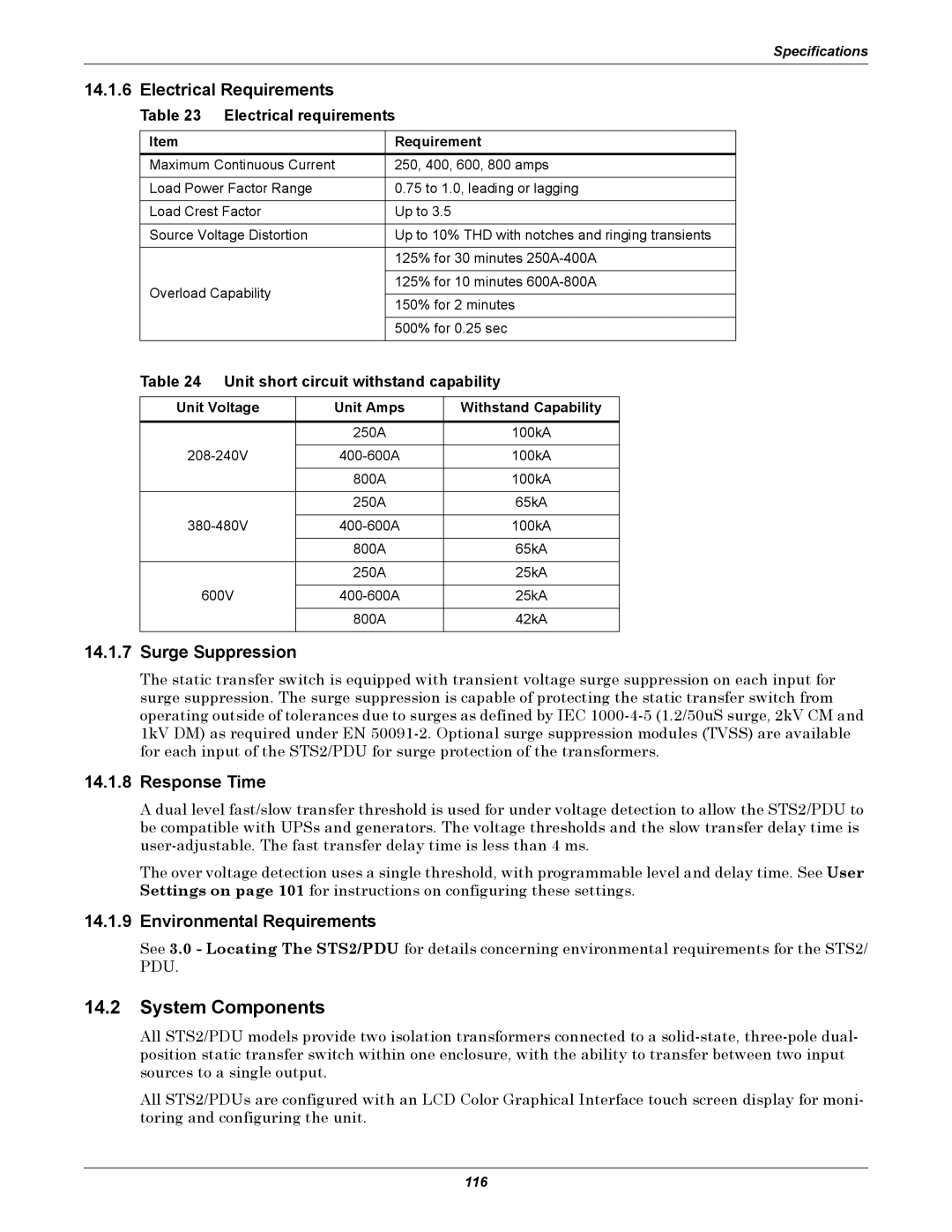
Table 23 Electrical requirements
Item | Requirement | |
Maximum Continuous Current | 250, 400, 600, 800 amps | |
|
| |
Load Power Factor Range | 0.75 to 1.0, leading or lagging | |
|
| |
Load Crest Factor | Up to 3.5 | |
|
| |
Source Voltage Distortion | Up to 10% THD with notches and ringing transients | |
|
| |
| 125% for 30 minutes | |
|
| |
Overload Capability | 125% for 10 minutes | |
| ||
150% for 2 minutes | ||
| ||
|
| |
| 500% for 0.25 sec | |
|
|
Table 24 Unit short circuit withstand capability
Unit Voltage | Unit Amps | Withstand Capability |
|
|
|
| 250A | 100kA |
|
|
|
100kA | ||
|
|
|
| 800A | 100kA |
|
|
|
| 250A | 65kA |
|
|
|
100kA | ||
|
|
|
| 800A | 65kA |
|
|
|
| 250A | 25kA |
|
|
|
600V | 25kA | |
|
|
|
| 800A | 42kA |
|
|
|
14.1.7Surge Suppression
The static transfer switch is equipped with transient voltage surge suppression on each input for surge suppression. The surge suppression is capable of protecting the static transfer switch from operating outside of tolerances due to surges as defined by IEC
14.1.8Response Time
A dual level fast/slow transfer threshold is used for under voltage detection to allow the STS2/PDU to be compatible with UPSs and generators. The voltage thresholds and the slow transfer delay time is
The over voltage detection uses a single threshold, with programmable level and delay time. See User Settings on page 101 for instructions on configuring these settings.
14.1.9Environmental Requirements
See 3.0 - Locating The STS2/PDU for details concerning environmental requirements for the STS2/ PDU.
14.2System Components
All STS2/PDU models provide two isolation transformers connected to a
All STS2/PDUs are configured with an LCD Color Graphical Interface touch screen display for moni- toring and configuring the unit.
116