Lincoln Electric SVM114-C service manual Troubleshooting and Repair

Models: SVM114-C

1 111
Download 111 pages 23.31 Kb
Page 48
Image 48

Return to Section TOC

Return to Section TOC

Return to Section TOC

Return to Section TOC

Return to Master TOC

Return to Master TOC

Return to Master TOC

Return to Master TOC

F-10

TROUBLESHOOTING AND REPAIR

F-10

GAS SOLENOID VALVE AND SOLENOID PC BOARD TEST

(continued)

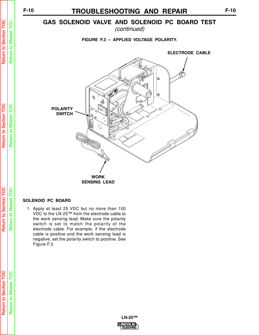
FIGURE F.3 – APPLIED VOLTAGE POLARITY.

ELECTRODE CABLE

POLARITY

SWITCH

WORK

SENSING LEAD

SOLENOID PC BOARD

1.Apply at least 25 VDC but no more than 100 VDC to the LN-25™ from the electrode cable to the work sensing lead. Make sure the polarity switch is set to match the polarity of the electrode cable. For example, if the electrode cable is positive and the work sensing lead is negative, set the polarity switch to positive. See Figure F.3.

LN-25™

Page 48
Image 48
Lincoln Electric SVM114-C service manual Troubleshooting and Repair