Return to Section TOC
Return to Section TOC
Return to Master TOC
Return to Master TOC
F-28 TROUBLESHOOTING AND REPAIR F-28
CONTACTOR & CONTACTOR PC BOARD TEST (continued)
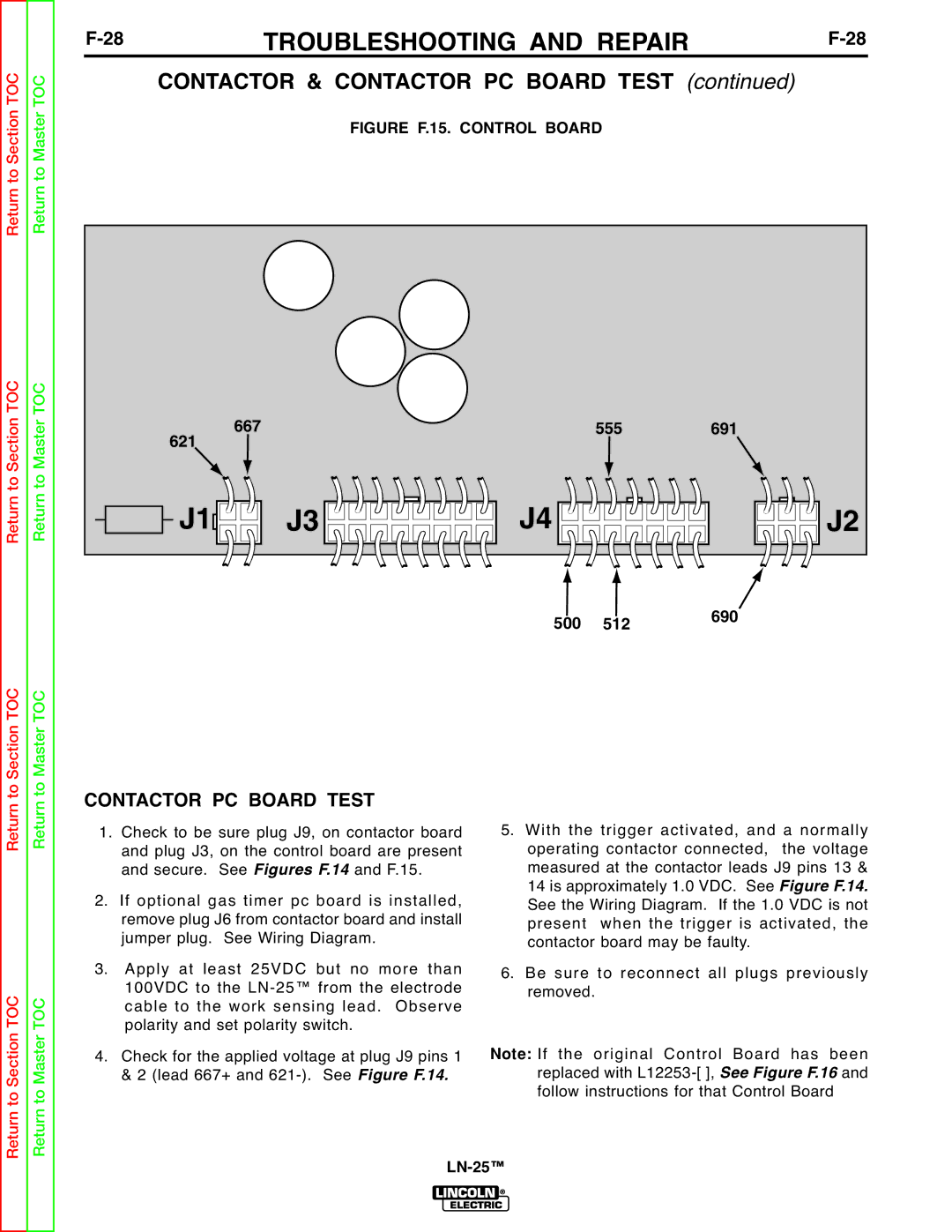
FIGURE F.15. CONTROL BOARD
667 | 555 | 691 |
621
J1 | J3 | J4 | J2 |
500 | 512 | 690 |
|
Return to Section TOC
to Section TOC
Return to Master TOC
to Master TOC
CONTACTOR PC BOARD TEST
1. Check to be sure plug J9, on contactor board and plug J3, on the control board are present and secure. See Figures F.14 and F.15.
2. If optional gas timer pc board is installed, remove plug J6 from contactor board and install jumper plug. See Wiring Diagram.
3. Apply at least 25VDC but no more than 100VDC to the
4. Check for the applied voltage at plug J9 pins 1 & 2 (lead 667+ and
5.With the trigger activated, and a normally operating contactor connected, the voltage measured at the contactor leads J9 pins 13 & 14 is approximately 1.0 VDC. See
See the Wiring Diagram. If the 1.0FigureVDC isF.not14. present when the trigger is activated, the contactor board may be faulty.
6.Be sure to reconnect all plugs previously removed.
If the original Control Board has been
Note: replaced with
Return
Return