Return to Section TOC
Return to Section TOC
Section TOC
Return to Master TOC
Return to Master TOC
Master TOC
THEORY OF OPERATION | |||
| GENERAL DESCRIPTION | voltage. It is designed for maximum versatility in |
|
|
| a variety of field applications. It can be used with |
|
The | most constant voltage or constant current DC | |
power sources without the need of a control | ||
feeder designed to operate from a DC arc | ||
cable. | ||
| ||
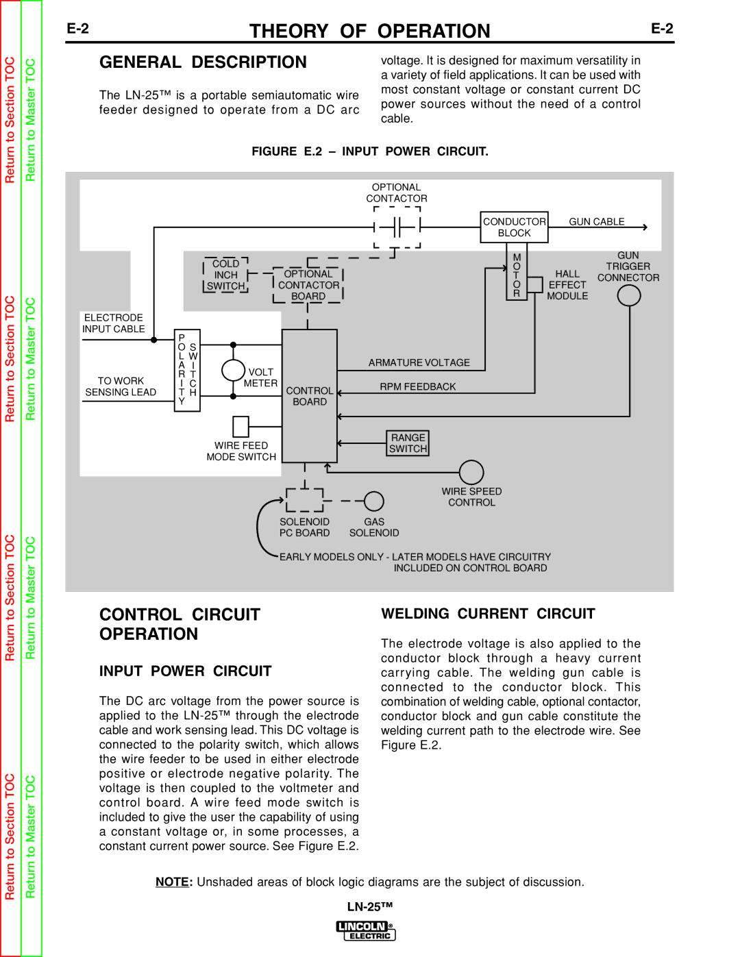
FIGURE E.2 – INPUT POWER CIRCUIT. | ||
|
|
|
| OPTIONAL |
|
|
|
|
|
| CONTACTOR |
|
|
|
|
|
| CONDUCTOR | GUN CABLE | |
|
|
|
| BLOCK |
|
|
| COLD |
|
| M |
| GUN |
|
| OPTIONAL | O | HALL | TRIGGER | |
| INCH |
| T | CONNECTOR | ||
| SWITCH | CONTACTOR | O | EFFECT |
| |
|
|
| BOARD | R | MODULE |
|
ELECTRODE |
|
|
|
|
|
|
INPUT CABLE | P |
|
|
|
|
|
|
|
|
|
|
| |
| O S |
|
|
|
|
|
| L W |
|
| ARMATURE VOLTAGE |
|
|
| A I | VOLT |
|
|
| |
TO WORK | R T |
|
|
|
| |
I C | METER | CONTROL | RPM FEEDBACK |
|
| |
SENSING LEAD | T H |
|
|
| ||
|
|
|
| |||
| Y |
| BOARD |
|
|
|
| WIRE FEED |
| RANGE |
|
| |
|
| SWITCH |
|
| ||
| MODE SWITCH |
|
|
| ||
|
|
|
|
| ||
|
|
|
| WIRE SPEED |
|
|
|
|
|
| CONTROL |
|
|
|
|
| SOLENOID | GAS |
|
|
|
|
| PC BOARD | SOLENOID |
|
|
|
|
| EARLY MODELS ONLY - LATER MODELS HAVE CIRCUITRY |
| ||
|
|
|
| INCLUDED ON CONTROL BOARD |
| |
Return to
to Section TOC
Return to
to Master TOC
CONTROL CIRCUIT
OPERATION
INPUT POWER CIRCUIT
The DC arc voltage from the power source is applied to the
WELDING CURRENT CIRCUIT
The electrode voltage is also applied to the conductor block through a heavy current carrying cable. The welding gun cable is connected to the conductor block. This combination of welding cable, optional contactor, conductor block and gun cable constitute the welding current path to the electrode wire. See Figure E.2.
Return
Return
NOTE: Unshaded areas of block logic diagrams are the subject of discussion.