Return to Section TOC
Return to Master TOC
F-48 TROUBLESHOOTING AND REPAIR F-48
DRIVE MOTOR AND GEARBOX REPLACEMENT AND ACCESS TO
HALL EFFECT MODULE (continued)
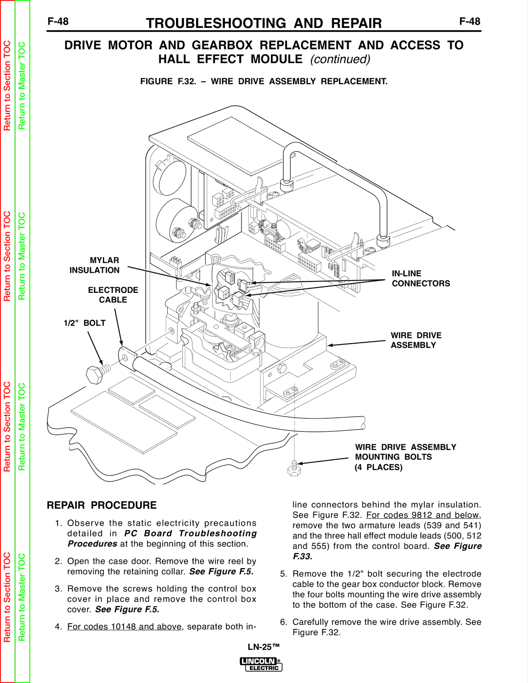
FIGURE F.32. – WIRE DRIVE ASSEMBLY REPLACEMENT.
Return to Section TOC
Return to Section TOC
Return to Master TOC
Return to Master TOC
MYLAR
INSULATION
ELECTRODE
CABLE
1/2" BOLT
CONNECTORS
WIRE DRIVE
ASSEMBLY
WIRE DRIVE ASSEMBLY MOUNTING BOLTS
(4 PLACES)
Return to Section TOC
Return to Master TOC
REPAIR PROCEDURE |
| line connectors behind the mylar insulation. | |
1. | Observe the static electricity precautions |
| See Figure F.32. For codes 9812 and below, |
| remove the two armature leads (539 and 541) | ||
| detailed in PC Board Tr ubleshooting |
| and the three hall effect module leads (500, 512 |
2. | Procedures at the beginning of this section. |
| and 555) from the control board. See Figure |
Open the case door. Remove the wire reel by |
| F.33. | |
3. | removing the retaining collar. See Figure F.5. | 5. Remove the 1/2" bolt securing the electrode | |
Remove the screws holding the control box |
| cable to the gear box conductor block. Remove | |
| cover in place and remove the control box |
| the four bolts mounting the wire drive assembly |
| cover. See Figure F.5. |
| to the bottom of the case. See Figure F.32. |
4. | For codes 10148 and above, separate both in- | 6. Carefully remove the wire drive assembly. See | |
| Figure F.32. | ||
|
|
| |