OPERATION |
Return to Section TOC
Return to Section TOC
Return to Section TOC
Return to Section TOC
Return to Master TOC
Return to Master TOC
Return to Master TOC
Return to Master TOC
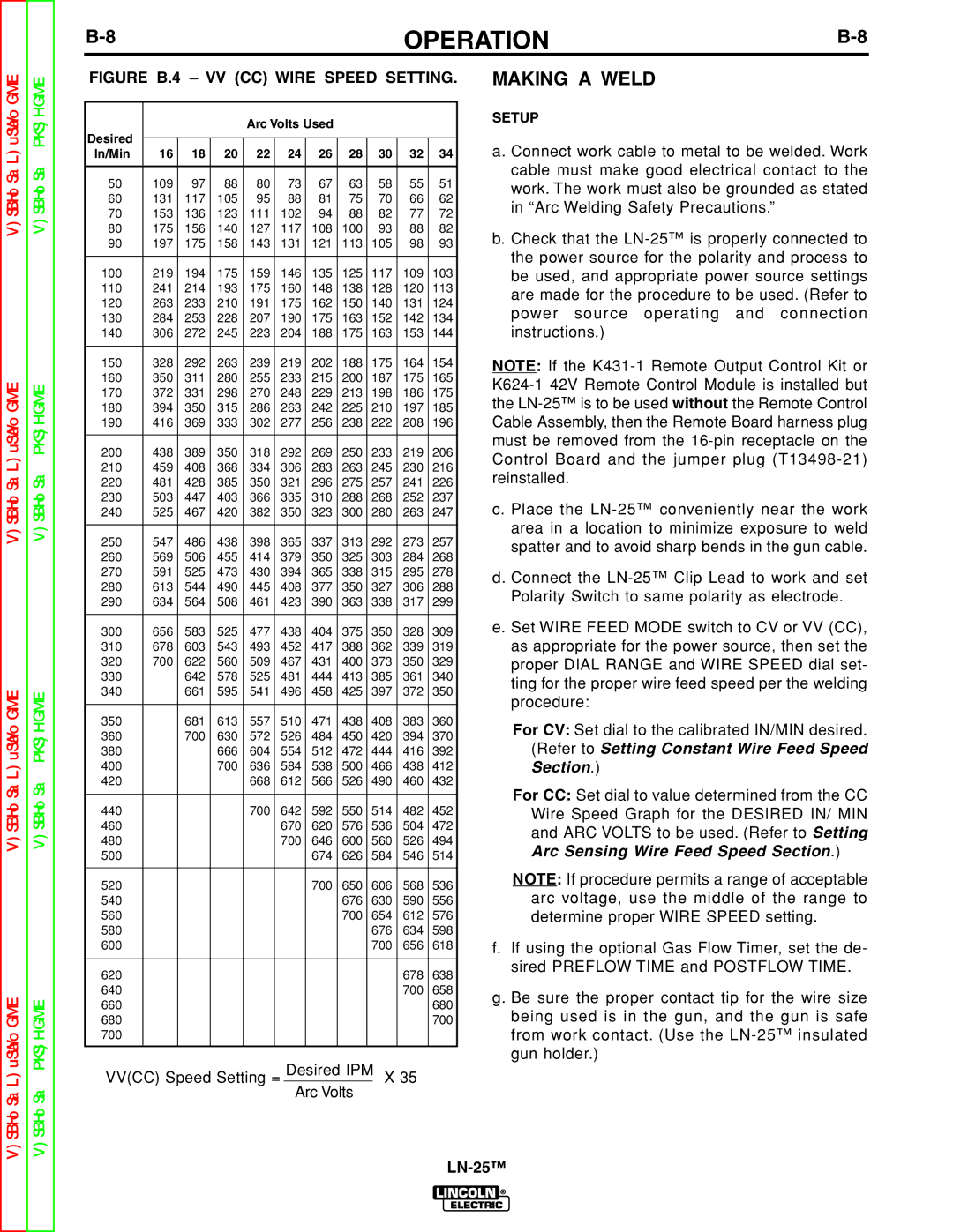
FIGURE B.4 – VV (CC) WIRE SPEED SETTING.
|
|
|
| Arc Volts Used |
|
|
|
| ||
Desired |
|
|
|
|
|
|
|
|
|
|
|
|
|
|
|
|
|
|
|
| |
In/Min | 16 | 18 | 20 | 22 | 24 | 26 | 28 | 30 | 32 | 34 |
|
|
|
|
|
|
|
|
|
|
|
50 | 109 | 97 | 88 | 80 | 73 | 67 | 63 | 58 | 55 | 51 |
60 | 131 | 117 | 105 | 95 | 88 | 81 | 75 | 70 | 66 | 62 |
70 | 153 | 136 | 123 | 111 | 102 | 94 | 88 | 82 | 77 | 72 |
80 | 175 | 156 | 140 | 127 | 117 | 108 | 100 | 93 | 88 | 82 |
90 | 197 | 175 | 158 | 143 | 131 | 121 | 113 | 105 | 98 | 93 |
|
|
|
|
|
|
|
|
|
|
|
100 | 219 | 194 | 175 | 159 | 146 | 135 | 125 | 117 | 109 | 103 |
110 | 241 | 214 | 193 | 175 | 160 | 148 | 138 | 128 | 120 | 113 |
120 | 263 | 233 | 210 | 191 | 175 | 162 | 150 | 140 | 131 | 124 |
130 | 284 | 253 | 228 | 207 | 190 | 175 | 163 | 152 | 142 | 134 |
140 | 306 | 272 | 245 | 223 | 204 | 188 | 175 | 163 | 153 | 144 |
|
|
|
|
|
|
|
|
|
|
|
150 | 328 | 292 | 263 | 239 | 219 | 202 | 188 | 175 | 164 | 154 |
160 | 350 | 311 | 280 | 255 | 233 | 215 | 200 | 187 | 175 | 165 |
170 | 372 | 331 | 298 | 270 | 248 | 229 | 213 | 198 | 186 | 175 |
180 | 394 | 350 | 315 | 286 | 263 | 242 | 225 | 210 | 197 | 185 |
190 | 416 | 369 | 333 | 302 | 277 | 256 | 238 | 222 | 208 | 196 |
|
|
|
|
|
|
|
|
|
|
|
200 | 438 | 389 | 350 | 318 | 292 | 269 | 250 | 233 | 219 | 206 |
210 | 459 | 408 | 368 | 334 | 306 | 283 | 263 | 245 | 230 | 216 |
220 | 481 | 428 | 385 | 350 | 321 | 296 | 275 | 257 | 241 | 226 |
230 | 503 | 447 | 403 | 366 | 335 | 310 | 288 | 268 | 252 | 237 |
240 | 525 | 467 | 420 | 382 | 350 | 323 | 300 | 280 | 263 | 247 |
|
|
|
|
|
|
|
|
|
|
|
250 | 547 | 486 | 438 | 398 | 365 | 337 | 313 | 292 | 273 | 257 |
260 | 569 | 506 | 455 | 414 | 379 | 350 | 325 | 303 | 284 | 268 |
270 | 591 | 525 | 473 | 430 | 394 | 365 | 338 | 315 | 295 | 278 |
280 | 613 | 544 | 490 | 445 | 408 | 377 | 350 | 327 | 306 | 288 |
290 | 634 | 564 | 508 | 461 | 423 | 390 | 363 | 338 | 317 | 299 |
|
|
|
|
|
|
|
|
|
|
|
300 | 656 | 583 | 525 | 477 | 438 | 404 | 375 | 350 | 328 | 309 |
310 | 678 | 603 | 543 | 493 | 452 | 417 | 388 | 362 | 339 | 319 |
320 | 700 | 622 | 560 | 509 | 467 | 431 | 400 | 373 | 350 | 329 |
330 |
| 642 | 578 | 525 | 481 | 444 | 413 | 385 | 361 | 340 |
340 |
| 661 | 595 | 541 | 496 | 458 | 425 | 397 | 372 | 350 |
|
|
|
|
|
|
|
|
|
|
|
350 |
| 681 | 613 | 557 | 510 | 471 | 438 | 408 | 383 | 360 |
360 |
| 700 | 630 | 572 | 526 | 484 | 450 | 420 | 394 | 370 |
380 |
|
| 666 | 604 | 554 | 512 | 472 | 444 | 416 | 392 |
400 |
|
| 700 | 636 | 584 | 538 | 500 | 466 | 438 | 412 |
420 |
|
|
| 668 | 612 | 566 | 526 | 490 | 460 | 432 |
|
|
|
|
|
|
|
|
|
|
|
440 |
|
|
| 700 | 642 | 592 | 550 | 514 | 482 | 452 |
460 |
|
|
|
| 670 | 620 | 576 | 536 | 504 | 472 |
480 |
|
|
|
| 700 | 646 | 600 | 560 | 526 | 494 |
500 |
|
|
|
|
| 674 | 626 | 584 | 546 | 514 |
|
|
|
|
|
|
|
|
|
|
|
520 |
|
|
|
|
| 700 | 650 | 606 | 568 | 536 |
540 |
|
|
|
|
|
| 676 | 630 | 590 | 556 |
560 |
|
|
|
|
|
| 700 | 654 | 612 | 576 |
580 |
|
|
|
|
|
|
| 676 | 634 | 598 |
600 |
|
|
|
|
|
|
| 700 | 656 | 618 |
|
|
|
|
|
|
|
|
|
|
|
620 |
|
|
|
|
|
|
|
| 678 | 638 |
640 |
|
|
|
|
|
|
|
| 700 | 658 |
660 |
|
|
|
|
|
|
|
|
| 680 |
680 |
|
|
|
|
|
|
|
|
| 700 |
700 |
|
|
|
|
|
|
|
|
|
|
|
|
|
|
|
|
|
|
|
|
|
VV(CC) Speed Setting = Desired IPM X 35 Arc Volts
MAKING A WELD
SETUP
a. Connect work cable to metal to be welded. Work cable must make good electrical contact to the work. The work must also be grounded as stated in “Arc Welding Safety Precautions.”
b. Check that the
NOTE: If the
c. Place the
d. Connect the
e. Set WIRE FEED MODE switch to CV or VV (CC), as appropriate for the power source, then set the proper DIAL RANGE and WIRE SPEED dial set- ting for the proper wire feed speed per the welding procedure:
For CV: Set dial to the calibrated IN/MIN desired. (Refer to Setting Constant Wire Feed Speed Section.)
For CC: Set dial to value determined from the CC Wire Speed Graph for the DESIRED IN/ MIN and ARC VOLTS to be used. (Refer to Setting Arc Sensing Wire Feed Speed Section.)
NOTE: If procedure permits a range of acceptable arc voltage, use the middle of the range to determine proper WIRE SPEED setting.
f.If using the optional Gas Flow Timer, set the de- sired PREFLOW TIME and POSTFLOW TIME.
g.Be sure the proper contact tip for the wire size being used is in the gun, and the gun is safe from work contact. (Use the