Section TOC
Master TOC
TROUBLESHOOTING AND REPAIR |
GAS SOLENOID VALVE AND/OR SOLENOID PC BOARD (IF
PRESENT) REPLACEMENT (continued)
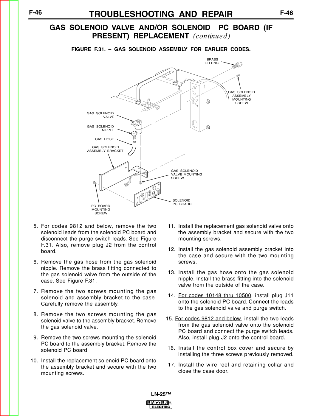
FIGURE F.31. – GAS SOLENOID ASSEMBLY FOR EARLIER CODES.
Return to
Return to Section TOC
Return to
Return to Master TOC
BRASS
FITTING
GAS SOLENOID
VALVE
GAS SOLENOID
NIPPLE
GAS HOSE
GAS SOLENOID
ASSEMBLY BRACKET
GAS SOLENOID
VALVE MOUNTING
SCREW
GAS SOLENOID
ASSEMBLY
MOUNTING
SCREW
PC BOARD MOUNTING SCREW
SOLENOID PC BOARD
Return to Section TOC
Return to Section TOC
Return to Master TOC
Return to Master TOC
5.For codes 9812 and below, remove the two solenoid leads from the solenoid PC board and disconnect the purge switch leads. See Figure F.31. Also, remove plug J2 from the control board.
6.Remove the gas hose from the gas solenoid nipple. Remove the brass fitting connected to the gas solenoid valve from the outside of the case. See Figure F.31.
7.Remove the two screws mounting the gas solenoid and assembly bracket to the case. Carefully remove the assembly.
8.Remove the two screws mounting the gas solenoid valve to the assembly bracket. Remove the gas solenoid valve.
9.Remove the two screws mounting the solenoid PC board to the assembly bracket. Remove the solenoid PC board.
10.Install the replacement solenoid PC board onto the assembly bracket and secure with the two mounting screws.
11.Install the replacement gas solenoid valve onto the assembly bracket and secure with the two mounting screws.
12.Install the gas solenoid assembly bracket into the case and secure with the two mounting screws.
13.Install the gas hose onto the gas solenoid nipple. Install the brass fitting into the solenoid valve from the outside of the case.
14.For codes 10148 thru 10500, install plug J11 onto the solenoid PC board. Connect the leads to the gas solenoid valve and purge switch.
15.For codes 9812 and below, install the two leads from the gas solenoid valve onto the solenoid PC board and connect the purge switch leads. Also, install plug J2 onto the control board.
16.Install the control box cover and secure by installing the three screws previously removed.
17.Install the wire reel and retaining collar and close the case door.