TOC
TOC
ELECTRICAL DIAGRAMS | ||
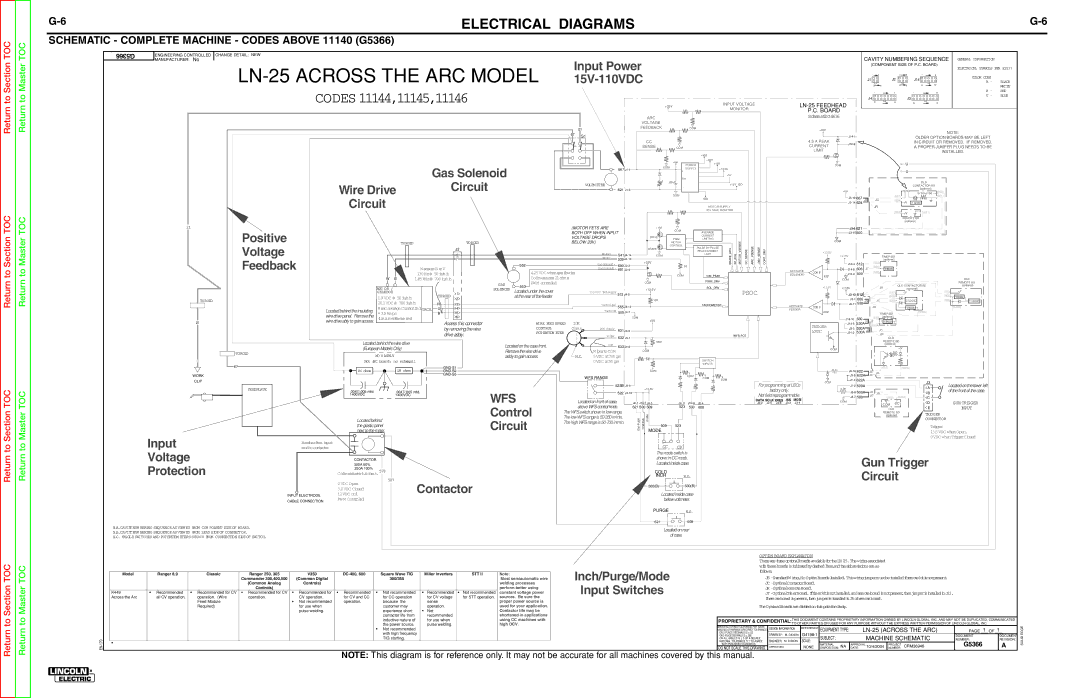
SCHEMATIC - COMPLETE MACHINE - CODES ABOVE 11140 (G5366) |
|
|
Return to Section
Return to Master
G5366 | ENGINEERING CONTROLLED | ||
MANUFACTURER: | No | ||
| |||
CHANGE DETAIL: NEW
| Input Power |
|
|
| |||
|
|
| |||||
CODES 11144,11145,11146 |
|
|
| +35V |
| INPUT VOLTAGE | |
|
|
|
|
|
| MONITOR | |
|
|
|
|
|
|
| |
|
|
|
| ARC |
|
|
|
|
|
|
| VOLTAGE |
|
|
|
|
|
| 21 | FEEDBACK |
| COM |
|
|
|
|
|
|
|
| |
|
| 67 | S1 |
|
|
|
|
|
|
|
|
|
|
| |
|
|
|
| CC |
|
|
|
|
|
|
| SENSE | COM |
|
|
|
|
|
|
|
|
| +VM |
|
|
|
|
| +Vin |
| +35V |
|
|
|
|
| POWER | +15V | |
|
|
|
|
|
| ||
| Gas Solenoid |
|
|
| COM |
| |
|
|
| 667 | SUPPLY | +13.5V | ||
|
|
| + | ||||
|
|
|
|
|
| +5V | |
|
|
|
| Vin |
| ||
Wire Drive | Circuit |
| VOLTM ETER |
| .05uF |
| +15V_ISO |
|
| - |
| ||||
|
| 621 |
|
| |||
|
| COM |
|
| |||
Circuit |
|
|
|
|
|
| ISO |
|
|
|
|
|
| MOTOR SUPPLY | |
|
|
|
|
|
| VOLTAGE MONITOR | |
P.C. BOARD
SchematicG4616
+35V
4.5 A PEAK | ||
CURRENT | ||
| ||
LIMIT |
| |
| COM | |
| +Vin | |
| ||
|
CAVITY NUMBERING SEQUENCE GENERAL INFORMATION |
| |||||
(COMPONENT SIDE OF P.C. BOARD) |
| |||||
|
|
|
|
| ELECTRICAL SYMBOLS PER E1537 | |
1 | 2 | 1 | 3 | 1 | 5 |
|
J1 |
| J2 |
| J14 | COLOR CODE |
|
|
| B - | BLACK | |||
|
|
|
|
| ||
3 | 4 | 4 | 6 | 6 | 10 | WHITE |
| ||||||
1 |
| 7 |
| 1 | R - | RED |
|
| 8 | BLUE | |||
J4 |
|
|
| J3 | U - | |
|
|
|
|
| ||
8 |
| 14 |
| 9 | 16 |
|
NOTE:
OLDER OPTION BOARDS MAY BE LEFT
IN CIRCUIT OR REMOVED. IF REMOVED,
A PROPER JUMPER PLUG NEEDS TO BE
INSTALLED.
![]() U
U
![]() U
U
|
|
|
| OLD |
|
|
|
|
| CONTACTOR BD |
|
|
|
|
| (optional) |
|
|
|
|
| to Timer Bd | (500) |
|
| (667) |
| (621) | |
667 JS |
|
|
| ||
JC | (624) | +V | C LOGIC |
| |
624 |
|
|
| ||
| JR |
|
|
|
|
|
| (624) | +V | (621) |
|
|
|
| REMOTE BD |
| |
|
|
| (optional) |
| |
Return to Section TOC
Return to Master TOC
21
TOROID
21
|
|
|
|
|
|
| (MOTOR FETS ARE |
| + VM | COM |
|
|
|
|
|
| |
Positive |
|
|
|
|
|
| BOTH OFF WHEN INPUT |
| AVERAGE |
|
|
|
|
| |||
|
|
|
|
|
|
|
|
|
|
|
|
| |||||
|
|
|
|
|
| VOLTAGE DROPS |
| DRIVE |
| CURRENT |
|
|
|
|
| ||
|
|
|
|
|
|
| PWM | LIMITING |
|
|
|
|
| ||||
TOROID |
|
| TOROID |
|
| BELOW 20V) |
|
| MOTOR |
| IM AVG MOTOR VSENSE |
|
|
|
| ||
Voltage |
|
|
|
|
|
|
|
|
|
| CONTROL | PULSE BY PULSE |
| ARC VSENSE | +35V SENSE |
| |
|
|
| J2 |
|
|
|
|
| BRAKE |
|
|
| |||||
|
|
|
|
|
|
|
|
| PEAK CURRENT |
|
| ||||||
|
|
| 8 |
|
|
| Motor+ | COM |
| LIMIT |
|
| |||||
|
|
|
|
|
| Motor- |
| BRAKEDRV | SENSECC | CONTDRV | |||||||
Feedback |
|
|
| 7 |
|
|
| 539 |
|
| |||||||
|
|
|
|
|
|
| +35V |
| |||||||||
|
|
|
|
| 552 |
| GasSolenoid+ | 690 | .05 | ||||||||
|
| MeasureBtoU |
|
|
|
|
|
|
|
|
|
| |||||
|
|
|
| 4.25VDC whengasflowing | GasSolenoid- | 691 |
|
|
|
|
|
|
|
| |||
|
|
| 130Hz@ 50in/min |
|
|
|
|
| COM | VIM_PEAK |
|
|
|
|
| ||
| W B | 1.85kHz@ 700in/min |
|
| Coilmeasures21ohms |
|
|
|
|
|
|
|
|
| |||
|
|
|
|
|
|
|
| PWM_DRV |
|
|
|
|
| ||||
|
|
|
|
| GAS | PWM controled |
|
|
| COM |
|
|
|
|
|
| |
|
|
|
|
|
|
|
|
|
|
|
|
|
|
| |||
| MOT OR / |
|
|
| 553 |
|
|
|
|
| SOL_DRV |
|
|
|
|
| |
|
|
|
| SOLENOID |
|
|
| +13.5V |
|
|
|
|
|
| |||
|
|
|
| Locatedunder thecover |
|
|
|
|
| PSOC |
|
| |||||
| GEARBOX |
| TOROID | 1 |
|
| 13.5VDC TachSupply | 512 |
|
|
|
|
|
| |||
| 1.9VDC @ 50in/min |
| 2 |
| at therear of thefeeder |
|
|
| 10K |
|
|
|
|
|
|
| |
|
|
|
|
|
|
|
|
|
|
|
|
|
|
| |||
| 20.1VDC @ 700in/min |
|
|
|
|
|
|
|
|
|
|
|
|
|
| ||
| R | 3 |
|
|
| TachSignal | 555 |
|
| TACHOMETER |
|
|
|
|
| ||
|
|
|
|
|
|
|
|
|
|
|
|
| |||||
Locatedbehindtheinsulating | 8secaverageCurrentlmitTACH. U | 4 |
|
|
| TachCOM | 500 |
|
|
|
|
|
|
|
| ||
(Limitissoftwareset)=3.5Amps |
| B | 5 |
|
|
|
|
|
|
|
|
|
|
| |||
wiredrivepanel. Removethe |
| 6 |
|
|
|
|
| COM |
|
|
|
|
|
|
| ||
wiredriveably togainaccess. |
|
| Access this connector |
| WIRE FEED SPEED | 10K |
|
| +5V |
|
|
|
|
|
|
| |
|
|
|
|
|
|
|
|
|
|
|
|
|
| ||||
|
|
| by removingthewire |
| CONTROL | Ohms | POT Supply | 631 |
|
|
|
|
|
|
|
| |
|
|
| driveasbly. |
| POTENTIOM ETER | 1 | W iper |
|
|
|
| WFS POT |
|
|
| ||
|
|
|
|
| 2 | 632 |
|
|
|
|
|
| |||||
|
| ||
|
| ||
|
| COM | |
| +13.5V | +13.5V | |
|
| ||
|
| ||
ACTIVATE | COM P | ||
SOLENOID | |||
REF | |||
| COM | ||
|
| ||
| +13.5V | +13.5V | |
|
| ||
|
| ||
ACTIVATE | COM P | ||
| |||
FEEDER |
| ||
REF |
| ||
|
| ||
|
| ||
| TRIGGER | ||
| |||
| LOGIC |
621 ![]()
![]()
![]()
![]()
![]()
![]()
![]()
![]() 500
500 ![]()
![]()
![]()
![]()
![]()
![]()
![]()
|
|
|
|
|
|
|
|
|
|
|
|
|
|
|
|
|
|
|
|
|
|
|
|
|
|
|
|
|
|
|
|
|
|
|
|
|
|
| TIMER BD |
|
|
|
|
|
|
|
|
|
|
|
|
|
| ||||
|
|
|
|
| (512) |
|
| (optional) |
|
|
|
|
|
|
|
|
|
|
|
|
|
| ||||||
512 |
|
|
|
|
|
|
|
|
|
|
|
|
|
|
|
|
| |||||||||||
|
|
|
|
|
|
|
|
|
|
|
|
|
|
|
|
|
|
|
|
|
|
| ||||||
| 606 |
| JT |
| (606) |
|
| TIMER |
|
|
|
|
|
|
|
|
|
|
|
|
|
|
| |||||
|
|
|
|
|
|
|
|
|
|
|
|
|
|
|
|
|
|
|
|
|
|
|
| |||||
|
|
| (500) |
|
|
|
|
|
|
|
|
|
|
|
|
|
|
|
| |||||||||
| 500 |
|
|
|
|
|
|
|
|
|
|
|
|
|
|
|
|
|
|
|
|
|
|
|
|
|
|
|
|
|
|
|
|
|
|
|
|
|
|
|
|
|
|
|
|
|
|
|
|
|
|
|
|
|
|
|
|
|
|
|
|
|
|
|
|
| JR | OLD CONTACTOR BD |
|
|
|
|
|
| ||||||||||||
|
|
|
|
|
|
|
|
|
| (optional) |
|
|
|
|
|
| ||||||||||||
|
|
|
|
|
|
|
|
|
|
|
|
|
|
|
|
|
|
|
|
|
|
|
|
|
|
|
| |
| 512 |
|
|
|
|
|
|
|
| (512) |
| +V |
|
|
|
|
|
|
|
| ||||||||
|
|
|
|
|
|
|
|
| (606) |
|
|
|
|
|
|
|
|
|
|
|
|
|
|
| ||||
| 606 |
|
|
|
|
|
|
|
|
|
|
|
|
|
| C LOGIC |
|
|
|
|
|
|
|
| ||||
| 530 | JS |
|
|
|
| JC | (530) |
|
|
|
|
|
|
|
|
|
| ||||||||||
|
|
|
|
|
|
|
|
|
|
|
|
|
|
|
|
|
|
|
|
|
|
|
|
|
|
|
| |
|
|
|
|
|
| JR |
|
|
|
|
|
|
| TIMER |
|
|
|
|
|
|
|
| ||||||
|
|
|
|
|
|
|
|
| TIMER BD |
|
|
|
|
|
| (530A) |
|
|
|
|
|
| ||||||
|
|
|
|
|
|
|
|
|
|
|
|
|
|
|
|
|
|
|
|
|
|
| ||||||
| 530 |
|
|
|
| (530) |
|
| (optional) |
|
|
|
|
|
|
|
|
|
|
|
|
|
| |||||
|
|
|
|
|
|
|
|
|
|
|
|
|
|
|
|
|
|
|
|
|
|
|
|
|
|
|
| |
| 530A | JS |
|
| JT |
|
| TIMER |
|
|
|
|
|
|
|
|
|
|
|
|
|
|
| |||||
|
|
|
| (530A) |
|
|
|
|
|
|
|
|
|
|
|
|
|
|
|
|
|
|
|
| ||||
| 530A | JS |
|
|
|
| JC |
|
|
|
|
|
|
|
|
|
|
|
|
|
|
|
|
|
|
| ||
| 530A |
|
|
|
|
|
|
|
|
|
|
|
|
|
|
|
|
|
|
|
|
|
| |||||
|
|
|
|
|
|
|
|
| JR |
|
|
|
|
|
|
|
|
|
|
|
|
|
|
| ||||
OLD
OLD
REMOTE BD (optional)
(512) +V
(606)
TIMER
(530)![]()

![]()
![]() C LOGIC
C LOGIC![]()
![]()
(530A)
WORK
CLIP
TOROID
67
Locatedbehindthewiredrive (EuropeanModels Only)
MO V ASBLY
Not aPC board; no schemati.

 1M ohms

 1M ohms


Locatedonthecasefront. Removethewiredrive asbly togainaccess.
3 | COM |
| 100K |
|
| 633 |
|
| |
|
|
|
| |
| WipertoCOM |
| COM |
|
|
|
|
| |
N.C. | 5VDC at700ipm |
|
| |
| 0VDC at50ipm | SWITCH |
| |
| INPUTS |
| ||
|
|
|
| |
|
|
| COM |
|
| WFS RANGE |
| COM |
|
|
| COM | COM | |
|
|
|
| |
|
|
| REMOTE BD | |
|
|
| (optional) |
|
COM |
|
|
| +V |
|
|
|
| |
| (622) | (622A) | ||
JS | JR |
| ||
622A | JC* |
| ||
622A |
|
|
| |
COM |
|
|
|
|
J3
FEEDPLATE
.0047/.005 mfd, | .0047/.005 mfd, |
1400VDC | 1400VDC |
523B J4-4
+13.5V
522J4-10
|
|
|
|
|
|
|
|
|
|
|
|
|
|
|
|
|
|
3.3K |
|
|
|
|
|
|
|
|
|
|
|
|
| ||||
|
|
|
|
|
|
| JS | JR |
|
|
|
|
|
|
| ||
|
|
|
|
|
|
| JC* |
|
|
|
|
|
|
|
|
|
|
![]()
![]() A
A
![]() B
B
Locatedonthelower left of thefront of thecase.
Locatedbehind theglasticpanel next tothemotor.
WFS
Control
Circuit
Locatedonfront of case, |
|
|
| ||||||||||||
aboveWFScontrol knob. |
|
|
|
|
|
|
|
|
|
|
|
|
| ||
621 500 509 |
|
| 523 | 530 608 | |||||||||||
TheWFSswitchshowninlowrange. |
|
|
|
|
|
|
|
|
|
|
|
|
|
|
|
|
| GasPurge ColdInch Mode |
|
|
|
|
|
|
|
|
|
| |||
|
|
|
|
|
|
|
|
|
|
|
| ||||
|
|
|
|
|
|
|
|
|
|
|
| ||||
|
|
|
|
|
|
|
|
|
|
| |||||
|
|
|
|
|
|
| 509 |
| 523 |
|
|
|
| ||
|
|
|
|
|
|
|
|
|
|
|
|
| |||
|
|
|
|
| MODE |
|
|
|
|
|
|
| |||
For programmingat LECo
factoryonly.
Not fieldreprogrammable.
DATA SCLK XRES /SS MOSI
|
|
| 500 |
|
|
|
|
| (500) (500A) | |||||
COM |
|
|
|
|
|
|
|
|
|
|
| |||
|
|
|
|
| COM | |||||||||
|
|
|
|
|
|
|
|
| ||||||
|
|
|
|
|
|
|
|
|
|
|
|
| ||
|
|
|
|
|
|
|
|
|
| OLD |
|
| ||
|
|
|
|
|
|
|
|
| REMOTE BD | |||||
|
|
|
|
|
|
|
|
| (optional) | |||||
|
|
|
|
|
|
|
|
|
|
|
|
|
|
|
C |
|
D | GUN TRIGGER |
E | INPUT |
TRIGGER
CONNECTOR
Trigger
13.5VDC whenOpen, 0VDC whenTriggerClosed
Input
Voltage
Protection
Bussbarfrom input |
|
| |
studtocontactor |
|
| |
| CONTACTOR |
| |
| 300A 60% |
| |
| 250A 100% |
| |
| Coilmeasures4.4ohms.578 |
| |
| 0VDC Open | 507 | |
INPUT ELECTRODE | Contactor | ||
12VDC coil | |||
| 3.0VDC Closed |
| |
CABLE CONNECTION | PWM Controled |
| |
|
|
CC CV
Themodeswitchis showninCCmode. Locatedinsidecase.
COLD
INCH N.O.
500(B)![]()
![]()
![]() 530(B)
530(B)
Locatedinsidecase belowvoltmeter.
PURGE N.O.
Gun Trigger Circuit
Return to Section TOC
Return to Section TOC
Return to Master TOC
Return to Master TOC
|
| N.A.CAVITY NUM BERING SEQUENCE AS VIEWED FROM COM PONENT SIDE OF BOARD. |
|
|
|
|
|
|
|
|
|
|
| 621 |
|
|
|
|
|
|
|
|
|
| 608 |
|
|
|
|
|
|
|
|
|
|
|
|
|
|
|
|
| |||
|
|
|
|
|
|
|
|
|
|
|
|
|
|
|
|
|
|
|
|
|
|
|
|
|
|
|
|
|
|
|
|
|
|
|
|
| |||||||||
|
|
|
|
|
|
|
|
|
|
|
|
|
| Locatedonrear |
|
|
|
|
|
|
|
|
|
|
|
|
|
| |||||||||||||||||
|
| N.B.CAVITY NUM BERING SEQUENCE AS VIEWED FROM LEAD SIDE OF CONNECTOR. |
|
|
|
|
|
|
|
|
|
|
|
|
|
|
|
|
|
|
|
|
|
|
|
|
|
| |||||||||||||||||
|
|
|
|
|
|
|
|
|
|
|
|
|
|
|
|
| of case. |
|
|
|
|
|
|
|
|
|
|
|
|
|
| ||||||||||||||
|
| N.C. OGGLET SWITCHES AND POTENTIOM ETERS SHOWN FROM CONNECTION SIDE OF SWITCH. |
|
|
|
|
|
|
|
|
|
|
|
|
|
|
|
|
|
|
|
|
|
|
|
|
|
|
|
|
| ||||||||||||||
|
|
|
|
|
|
|
|
|
|
|
|
|
|
|
|
|
|
|
|
|
|
|
|
|
|
|
|
|
|
|
|
|
|
|
|
|
|
|
|
|
| ||||
|
|
|
|
|
|
|
|
|
|
|
|
|
|
|
|
|
|
|
|
|
|
|
|
|
|
|
|
|
|
|
|
|
|
|
|
|
|
|
|
|
|
| |||
|
|
|
|
|
|
|
|
|
|
|
|
|
|
|
|
|
|
|
|
|
|
|
|
|
|
|
|
|
|
|
|
|
|
|
|
|
|
|
|
|
|
|
|
|
|
|
|
|
|
|
|
|
|
|
|
|
|
|
|
|
|
|
|
|
|
|
|
|
|
|
|
|
|
|
|
| OPTION BOARD EXPLANATION |
|
|
|
|
|
|
|
|
|
|
| |||
|
|
|
|
|
|
|
|
|
|
|
|
|
|
|
|
|
|
|
|
|
|
|
|
|
|
|
|
|
|
|
|
|
|
|
|
|
| ||||||||
|
|
|
|
|
|
|
|
|
|
|
|
|
|
|
|
|
|
|
|
|
|
|
|
|
|
|
|
|
|
| withtheseboardssindicatedbydashedlines.andtheabbreviationsareas |
|
|
|
|
|
|
| |||||||
|
|
|
|
|
|
|
|
|
|
|
|
|
|
| Inch/Purge/Mode |
|
|
|
|
|
|
|
|
|
| folows: |
|
|
|
|
|
|
|
|
|
|
|
| |||||||
|
| Model | Ranger 8,9 | Classic | Commander 300,400,500 | (Common Digital | 300/355 | Miller Inverters | STT II | Most semiautomatic wire |
|
|
|
|
|
|
|
|
|
|
|
| JS |
|
|
|
|
|
| ||||||||||||||||
|
| Ranger 250, 305 | V350 | Square Wave TIG | Note: |
|
|
|
|
|
|
|
|
|
|
|
|
|
|
|
|
|
|
|
|
|
|
|
|
|
|
|
|
|
|
|
| ||||||||
|
|
|
|
| (Common Analog | Controls) |
|
|
|
|
|
| welding processes |
| Input Switches |
|
|
|
|
|
|
|
|
|
|
| JC |
|
|
|
|
|
|
|
|
|
|
| |||||||
|
|
|
|
| Controls) |
|
|
|
|
|
|
| perform better using |
|
|
|
|
|
|
|
|
|
|
|
| JR |
|
|
|
|
|
|
|
|
|
|
| ||||||||
|
| K449 | Recommended | Recommended for CV | Recommended for CV | Recommended for | Recommended |
| Not recommended | Recommended | Not recommended | constant voltage power |
|
|
|
|
|
|
|
|
|
|
|
|
|
|
|
|
|
| |||||||||||||||
|
| Across the Arc | all CV operation. | operation. (Wire | operation. | CV operation. | for CV and CC |
| for CC operation | for CV voltage | for STT operation. | sources. Be sure the |
|
|
|
|
|
|
|
|
|
|
|
|
|
|
|
|
|
| Ifremoteboardispresent,thenjumpersinstaledinJ6ofremoteboard. |
|
|
|
|
|
|
| |||||||
|
|
|
| Feed Module |
| Not recommended | operation. |
| because the | sense |
| proper power source is |
|
|
|
|
|
|
|
|
|
|
|
|
|
|
|
|
|
|
|
|
|
|
|
|
| ||||||||
|
|
|
|
|
|
|
|
|
|
|
|
|
|
|
|
|
|
|
|
|
|
|
|
|
|
|
|
|
|
|
|
|
|
|
|
|
|
| |||||||
|
|
|
| Required) |
| for use when |
|
| customer may | operation. |
| used for your application. |
|
|
|
|
|
|
|
|
|
|
|
|
|
|
|
|
| TheOptionalBoardsaredividedonthisprintforclarity. |
|
|
|
|
|
|
|
|
|
| |||||
|
|
|
|
|
| pulse welding. |
|
| experience short | Not |
| Contactor life may be |
|
|
|
|
|
|
|
|
|
|
|
|
|
|
|
|
|
|
|
|
|
|
|
|
|
|
|
|
|
|
|
| |
|
|
|
|
|
|
|
|
| contactor life from | recommended |
| shortened in applications |
|
|
|
|
|
|
|
|
|
|
|
|
|
|
|
|
|
|
|
|
|
|
|
|
|
|
|
|
|
|
|
| |
|
|
|
|
|
|
|
|
| inductive nature of | for use when |
| using CC machines with |
|
|
|
|
|
|
|
|
|
|
|
|
|
|
|
|
| PROPRIETARY & CONFIDENTIAL:THIS DOCUMENT CONTAINS PROPRIETARY INFORMATION OWNED BY LINCOLN GLOBAL, INC. AND MAY NOT BE DUPLICATED, COMMUNICATED |
| ||||||||||||||
|
|
|
|
|
|
|
|
| the power source. | pulse welding. |
| high OCV. |
|
|
|
|
|
|
|
|
|
|
|
|
|
|
|
|
|
|
| TO OTHER PARTIES OR USED FOR ANY PURPOSE WITHOUT THE EXPRESS WRITTEN PERMISSION OF LINCOLN GLOBAL, INC. |
|
|
|
| |||||||||
|
|
|
|
|
|
|
|
| Not recommended |
|
|
|
|
|
|
|
|
|
|
|
|
|
|
|
|
|
|
|
| MANUFACTURING TOLERANCE PER E2056 |
| DESIGN INFORMATION | REFERENCE: | EQUIPMENT TYPE: |
|
| 1 |
| 1 |
| EDGE | ||||
|
|
|
|
|
|
|
|
|
|
|
|
|
|
|
|
|
|
|
|
|
|
|
|
|
|
|
|
| UNLESS OTHERWISE SPECIFIED TOLERANCE: |
|
|
| |||||||||||||
|
|
|
|
|
|
|
|
| with high frequency |
|
|
|
|
|
|
|
|
|
|
|
|
|
|
|
|
|
|
|
| ON 2 PLACE DECIMALS IS ± .02 |
|
|
|
| PAGE ___ OF ___ | ||||||||||
|
|
|
|
|
|
|
|
|
|
|
|
|
|
|
|
|
|
|
|
|
|
|
|
|
|
|
|
|
| DRAWN BY: M. DIDION |
|
| |||||||||||||
|
|
|
|
|
|
|
|
|
|
|
|
|
|
|
|
|
|
|
|
|
|
|
|
|
|
|
|
| ON 3 PLACE DECIMALS IS ± .002 |
| SUBJECT: |
|
| MACHINE SCHEMATIC | DOCUMENT |
| DOCUMENT |
| |||||||
|
|
|
|
|
|
|
|
| TIG starting. |
|
|
|
|
|
|
|
|
|
|
|
|
|
|
|
|
|
|
|
| ON ALL ANGLES IS ± .5 OF A DEGREE |
|
|
|
|
| NUMBER: |
| REVISION: | SOLID | ||||||
|
|
|
|
|
|
|
|
|
|
|
|
|
|
|
|
|
|
|
|
|
|
|
|
|
|
|
| ENGINEER: M. DIDION | SCALE: |
|
| ||||||||||||||
|
|
|
|
|
|
|
|
|
|
|
|
|
|
|
|
|
|
|
|
|
|
|
|
|
|
|
|
|
| MATERIAL TOLERANCE ("t") TO AGREE |
|
|
|
|
|
| G5366 |
| A |
| |||||
|
|
|
|
|
|
|
|
|
|
|
|
|
|
|
|
|
|
|
|
|
|
|
|
|
|
|
|
|
| WITH PUBLISHED STANDARDS. |
|
|
| MATERIAL | APPROVAL |
| PROJECT |
| |||||||
|
|
|
|
|
|
|
|
|
|
|
|
|
|
|
|
|
|
|
|
|
|
|
|
|
|
|
|
|
|
|
|
|
|
| |||||||||||
|
|
|
|
|
|
|
|
|
|
|
|
|
|
|
|
|
|
|
|
|
|
|
|
|
|
|
|
|
| DO NOT SCALE THIS DRAWING |
| APPROVED: | NONE | DISPOSITION: NA | DATE: |
| 10/4/2004 | NUMBER: CRM36946 |
|
| |||||
NOTE: This diagram is for reference only. It may not be accurate for all machines covered by this manual.
¤