Return to Section TOC
Return to Master TOC
TROUBLESHOOTING AND REPAIR |
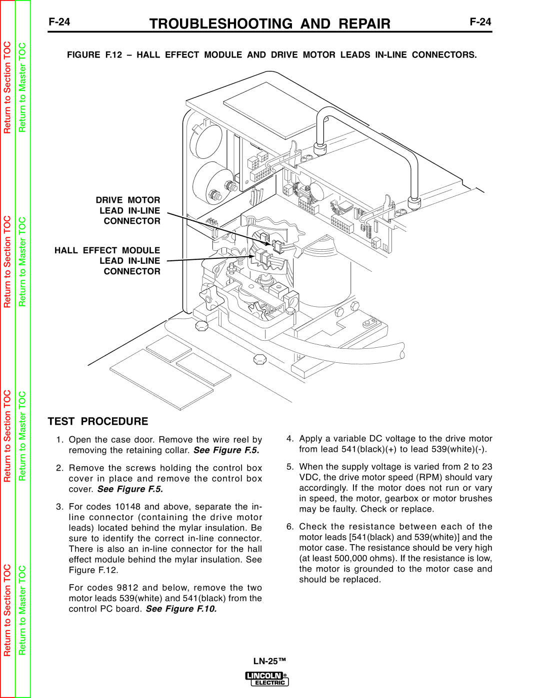
FIGURE F.12 – HALL EFFECT MODULE AND DRIVE MOTOR LEADS IN-LINE CONNECTORS.
Return to Section TOC
Return to Section TOC
to Section TOC
Return to Master TOC
Return to Master TOC
to Master TOC
DRIVE MOTOR
LEAD IN-LINE
CONNECTOR
HALL EFFECT MODULE
LEAD
CONNECTOR
TEST PROCEDURE
1. Open the case door. Remove the wire reel by removing the retaining collar. See Figure F.5.
2. Remove the screws holding the control box cover in place and remove the control box cover. See Figure F.5.
3. For codes 10148 and above, separate the in- line connector (containing the drive motor leads) located behind the mylar insulation. Be sure to identify the correct
For codes 9812 and below, remove the two motor leads 539(white) and 541(black) from the control PC board. See Figure F.10.
4.Apply a variable DC voltage to the drive motor from lead 541(black)(+) to lead
5.When the supply voltage is varied from 2 to 23 VDC, the drive motor speed (RPM) should vary accordingly. If the motor does not run or vary in speed, the motor, gearbox or motor brushes may be faulty. Check or replace.
6.Check the resistance between each of the motor leads [541(black) and 539(white)] and the motor case. The resistance should be very high (at least 500,000 ohms). If the resistance is low, the motor is grounded to the motor case and should be replaced.
Return
Return