Return to Section TOC
Return to Section TOC
Return to Section TOC
Return to Master TOC
Return to Master TOC
Return to Master TOC
TROUBLESHOOTING AND REPAIR |
CONTACTOR & CONTACTOR PC BOARD TEST (continued)
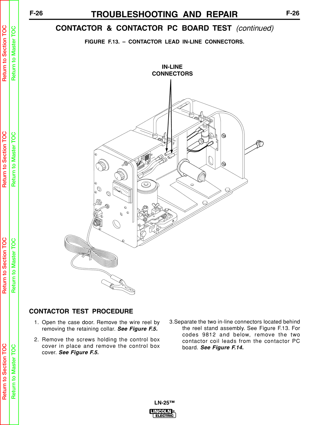
FIGURE F.13. – CONTACTOR LEAD IN-LINE CONNECTORS.
CONNECTORS
Return to Section TOC
Return to Master TOC
CONTACTOR TEST PROCEDURE
1.Open the case door. Remove the wire reel by removing the retaining collar. See Figure F.5.
2.Remove the screws holding the control box cover in place and remove the control box cover. See Figure F.5.
3.Separate the two