LN-9 Wire Feeder
Safety
LN-9 Wire Feeder
Electric Shock can kill
ARC Rays can burn
Fumes and Gases can be dangerous
Cylinder may explode if damaged
Iii
Précautions DE Sûreté
Master Table of Contents for ALL Sections
Table of Contents Installation Section
Installation
Technical Specifications LN-9
Width Height
Mounting the Wire Feed Unit
Installing the LN-9F Roll and 4-ROLL Models
Attaching the Wire Reel Stand
Mounting the Unit
Electrical Connections LN-9N, S and LN-9F
Power Input Cable Assembly
LN-9S Wire Feed Unit
Routing the Electrode
Figure A.2 Strain Relief Clamp
Figure A.4 LN-9F Control BOX Bottom View
Connecting the Power Input Cable Assembly to Power Sources
Figure A.5 for DC-250, DC-400 and CV-400, CV-500 l
Can kill
Figure A.6 Connection of LN-9 to DC-600 Power Sources
Figure A.7 Connection of LN-9 to DC-1000 Power Sources
Installation
Direct Work Lead Connection
Machine Grounding
Work Cable Connection
Table A.1 Work Cable Sizes
Connecting the GUN Cable to the Wire Feeder
Figure A.9 GUN Cable Connections
LN-9 Wire Feeder
Table of Contents Operation Section
Safety Instructions
Operation
DC Constant Voltage Power Sources
General Description
Recommended Processes and Equipment
Controls and Settings
Figure B.1 Wire Feeder Controls for LN-9N, NE, S, SE
Figure B.2 Wire Feeder Controls for LN-9F
LN-9F Control BOX Bottom View
Circuit Protection and Automatic Shutdown
Avoiding Grounding Lead Protector GLP Shutdown
Automatic Shutdown
Drive Roll Installation and Pressure Setting
Figure B.3 2 Roll Wire Feed Mechanism
Setting the Idler Roll Spring Pressure 2-ROLL Wire Drives
Setting the Idler Roll Pressure 4-ROLL Wire Drives
Operation
Figure B.4 Installing Drive Rolls on a 4-ROLL Feeder
Wire Loading
Loading and Feeding READI-REELS or Spools
Electrode Feeding and Brake Adjustment
When Using the Extension Assembly models LN-9NE and LN-9SE
Loading a 15 to 30 LB. Spool 12 Diameter
Figure B.6 Loading a 50 or 60 LB. Coil
Electrode Feeding
Adjust the Power Source
Pulse Power 500, DC650 PRO
SAM
Voltage Control Response
Adjust the LN-9 Controls
Starting Characteristics
Select Acceleration
Procedure AT END of Coil
Security of Weld Procedure Settings
Making a Weld
Table of Contents Accessories
Wire Reel Stands and Mountings
Optional Equipment and Accessories
Power Input Cable Assemblies K196, K595, K596
Auxiliary Equipment Contacts
50-60 LB. Wire Reel Assembly for Customer Mounting K299
Attaching the Wire Reel Stands
Wire Reel Door KIT M-11514
Spindle for READI-REELS and 2 I.D. Spools K162-H
60% Duty
GUN and Cable Assemblies
Table C.1 LN-9 GUN and Cable Assemblies
Process Model Electrode Rating
Dual Procedure KIT K319
Wire Feeder Accessories
Burnback Delay KIT K202
Pulse Power Filter Conversion KIT K442-1
Continuous Flux Feed Tank K320
Swivel Platform K178-1
Undercarriage K163
K320 Flux Tank Loading
Magnetic Separator K58
Mechanized Travel Power Pack K161-CABLE Length
Power Extended Wire Drive K392
Mechanized Hand Travel Unit K110
Cored Electrode
Table C.2 Drive Roll and Guide Tube Kits
Kit Roll Solid Steel Electrode
Aluminum Electrode
Table of Contents Maintenance
Safety Precautions
Routine Maintenance
Periodic Maintenance
GUN and Cable Maintenance
Figure D.1 LN-9 Connectors
Figure D.3 General Component Locations
Table of Contents Theory of Operation Section
Power Input Circuits
Theory of Operation
Trigger and Shutdown Circuit
Figure E.3 Trigger and Shutdown Circuit
ARC VOLTAGE, Wire Speed Control and Metering
Figure E.4 ARC VOLTAGE, Wire Speed Control and Metering
Printed Circuit Board Functions
LN-9 Wire Feeder
Table of Contents Troubleshooting & Repair Section
Troubleshooting & Repair
HOW to USE Troubleshooting Guide
PC Board Troubleshooting Procedures
PC Board can be damaged by static electricity
Troubleshooting Guide
Observe Safety Guidelines
Detailed in the beginning of this manual
Function Problems
Trigger
Troubleshooting & Repair
Troubleshooting Guide
Troubleshooting & Repair
Trigger Interlock Function Problems
Perform the T1 Transformer
Perform the T2 Transformer
Troubleshooting & Repair
Perform Out of Voltage Range
Feeding Problems
Welding Problems
Troubleshooting & Repair
Meter Function Problems
Bypass
Starting Problems
Troubleshooting & Repair
Problems Possible Areas
Symptoms Misadjustments Course of Action
T1 Transformer Test
Description
Materials Needed
Test Procedure
T1 Transformer Test
Figure F.2 Secondary Leads #601 and #602 AT Lead Splices
T2 Transformer Test
Figure F.3 Protection Circuit Troubleshooting Nameplate
T2 Transformer Test
Circuit Breaker
Lead Lead
Wire Drive Motor and Tach Feedback Test
Wire Drive Motor and Tach Feedback Test
Apply 115 VAC power
Tach Feedback Test Procedure
Figure F.7 Leads #525, #510, #555 on Control PC Board
Voltmeter Accuracy Test
Voltmeter Accuracy Test
Figure F.8 Voltmeter Connection Point
Return Return to Section TOC
Meter Circuit Accuracy Test
Meter Circuit Accuracy Test
Figure F.9 Meter PC Board Locations and Cover
Figure F.10 Meter PC Board Test Points
Test Meter PC Board Accuracy. All Models
Test Meter PC Board Accuracy. For LN9-H
Test Meter PC Board Accuracy. Metric Models Only
Metric Model Metric Range SET M/MIN Reading Test Voltmeter
Wire Speed Accuracy Test
Wire Speed Accuracy Test
Check for the proper drive roll revolutions per minute
OUT of Voltage Range Shut Down Test
OUT of Voltage Range Shut Down Test
Figure F.11 Voltage PC Board with Jumpers
Section TOC
General Power Supply Tests
General Power Supply Tests
Also perform the T1 Transformer Test
General Power Supply Checks
Digital Meter and Meter PC Board Removal Replacement
Replacement
Digital Meter and Meter PC Board Removal
Meter PC Board Removal
Digital Meter Removal Procedure
Replacement Procedure
Reed Switch CR2 Removal and Replacement
Reed Switch CR2 Removal and Replacement
Replacement
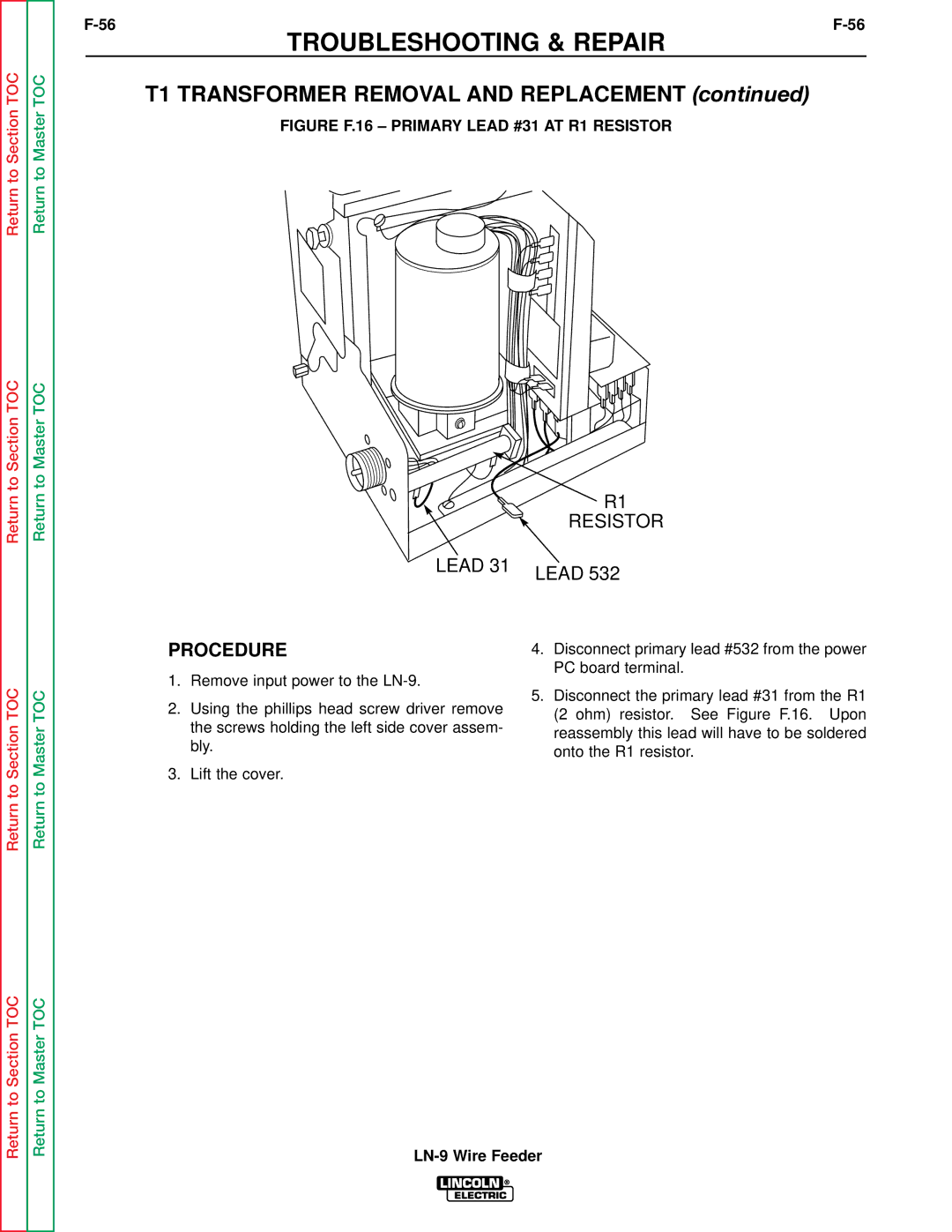
T1 Transformer Removal and Replacement
T1 Transformer Removal and Replacement
Figure F.16 Primary Lead #31 AT R1 Resistor
Lead
NUT and Screw Control PC Board 1CR Relay Phillips Screws
Terminal
Tach PC Board Removal and Replacement
Tach PC Board Removal and Replacement
Figure F.21 Tach Assembly Cover Screws
Phillips Screw Disc NUT Tach PC Board
Reassembly
Figure F.24 Tach Component Assembly
Drive Motor Removal and Replacement
Drive Motor Removal and Replacement
Figure F.25 TOP Motor Plate Screws
Nuts and Washers 4-ROLL Feeders
Mylar Insulator Glastic Mounting Board Bolts
Mounting Screws Insulators Gear BOX Assembly
Retest the LN-9 wire feeder
Retest After Repair
LN-9 Wire Feeder
Electrical Diagram Section
LN-9 Wire Feeder
Electrical Diagrams
LN-9
Operating Schematic
Meter Board L6687 Schematic
21145
Trigger Board M13861 Schematic
20031
Tachometer Schematic
19852