THEORY OF OPERATION | ||
|
|
|
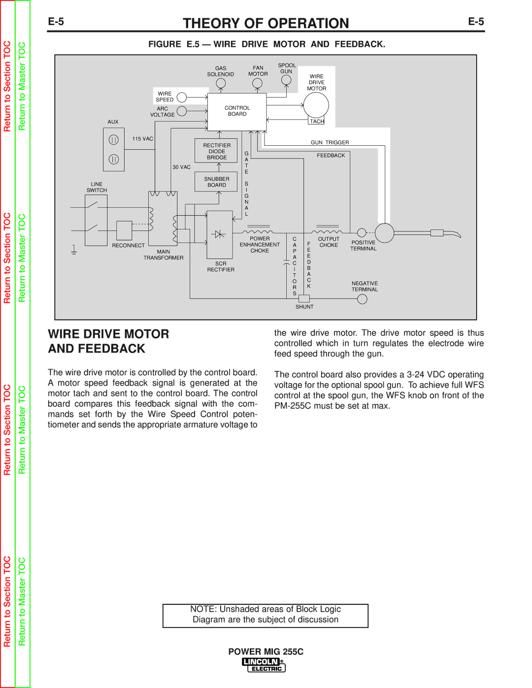
TOC | TOC | FIGURE E.5 — WIRE DRIVE MOTOR AND FEEDBACK. | |||||||
|
|
|
|
|
|
|
| ||
Section | Master |
| GAS | FAN | SPOOL |
|
|
| |
|
| GUN |
|
|
| ||||
| SOLENOID | MOTOR |
| WIRE |
| ||||
|
|
|
| ||||||
|
|
|
|
|
| ||||
|
|
|
|
| DRIVE |
| |||
WIRE |
|
|
|
| MOTOR |
| |||
to | to |
|
|
|
|
|
|
| |
SPEED |
|
|
|
|
|
|
| ||
Return | Return | ARC | CONTROL |
|
|
|
|
| |
VOLTAGE | BOARD |
|
|
|
|
| |||
AUX |
|
|
|
| TACH |
| |||
|
|
|
|
|
|
|
| ||
|
| 115 VAC |
|
|
|
|
| GUN TRIGGER |
|
|
|
| RECTIFIER |
|
|
|
|
| |
|
|
|
|
|
|
|
|
| |
|
|
| DIODE | G |
|
|
| FEEDBACK |
|
|
|
| BRIDGE |
|
|
|
| ||
|
|
| A |
|
|
|
| ||
|
|
|
|
|
|
|
| ||
|
|
|
|
|
|
|
|
| |
|
| 30 VAC |
| T |
|
|
|
|
|
|
|
|
| E |
|
|
|
|
|
|
| LINE | SNUBBER | S |
|
|
|
|
|
|
| BOARD |
|
|
|
|
| ||
|
| SWITCH |
| I |
|
|
|
|
|
|
|
|
| G |
|
|
|
|
|
|
|
|
| N |
|
|
|
|
|
TOC |
|
|
| A |
|
|
|
|
|
TOC |
|
| L |
|
|
|
|
| |
|
|
|
|
|
|
|
| ||
Section | Master |
|
| POWER |
| C | F | OUTPUT | POSITIVE |
RECONNECT |
| ENHANCEMENT | A | CHOKE | |||||
| TERMINAL | ||||||||
MAIN |
| CHOKE |
| P | E |
| |||
|
|
|
| ||||||
TRANSFORMER |
|
|
| A | E |
|
| ||
| SCR |
|
| C | D |
|
| ||
to | to |
|
|
| B |
|
| ||
| RECTIFIER |
|
| I |
|
| |||
|
|
|
| T | A |
|
| ||
Return | Return |
|
|
|
|
|
| ||
|
|
|
| O | C |
| NEGATIVE | ||
|
|
|
| R | K |
| |||
|
|
|
|
| TERMINAL | ||||
|
|
|
| S |
|
| |||
|
|
|
|
|
|
| |||
|
|
|
| SHUNT |
| ||||
|
|
|
|
|
|
| |||
|
| WIRE DRIVE MOTOR | the wire drive motor. The drive motor speed is thus |
|
| AND FEEDBACK | controlled which in turn regulates the electrode wire |
|
| feed speed through the gun. | |
|
|
| |
|
| The wire drive motor is controlled by the control board. | The control board also provides a |
TOC | TOC | A motor speed feedback signal is generated at the | voltage for the optional spool gun. To achieve full WFS |
motor tach and sent to the control board. The control | control at the spool gun, the WFS knob on front of the | ||
SectiontoReturn | MastertoReturn | board compares this feedback signal with the com- | |
mands set forth by the Wire Speed Control poten- |
| ||
|
|
| |
|
| tiometer and sends the appropriate armature voltage to |
|
Section TOC | Master TOC |
| |
to | to | NOTE: Unshaded areas of Block Logic | |
Diagram are the subject of discussion | |||
Return | Return | ||
| |||
POWER MIG 255C | |||
|
|