| INSTALLATION | ||
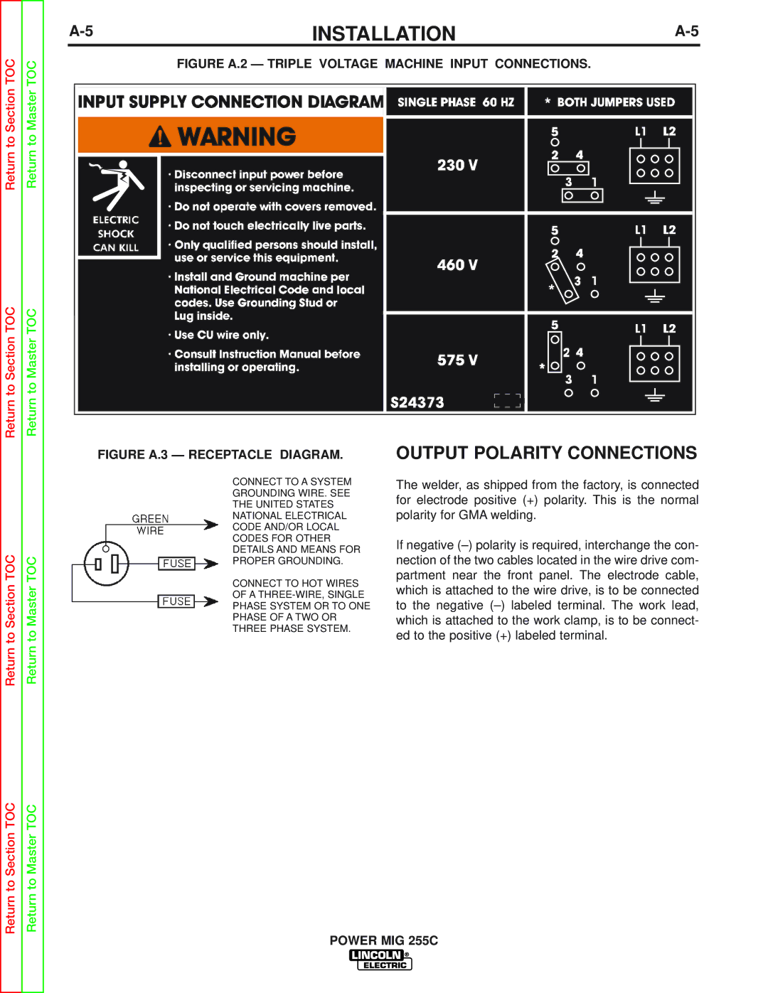
Return to Section TOC | Return to Master TOC | FIGURE A.2 — TRIPLE VOLTAGE MACHINE INPUT CONNECTIONS. |
|
|
| ||
Return to Section TOC | Return to Master TOC |
|
|
FIGURE A.3 — RECEPTACLE DIAGRAM. OUTPUT POLARITY CONNECTIONS
|
| CONNECT TO A SYSTEM | The welder, as shipped from the factory, is connected | |
|
| GROUNDING WIRE. SEE | for electrode positive (+) polarity. This is the normal | |
|
| THE UNITED STATES | ||
|
| polarity for GMA welding. | ||
|
| NATIONAL ELECTRICAL | ||
|
| CODE AND/OR LOCAL |
| |
|
| CODES FOR OTHER | If negative | |
TOC |
| DETAILS AND MEANS FOR | ||
TOC | nection of the two cables located in the wire drive com- | |||
PROPER GROUNDING. | ||||
CONNECT TO HOT WIRES | partment near the front panel. The electrode cable, | |||
Section | Master | which is attached to the work clamp, is to be connect- | ||
PHASE OF A TWO OR | ||||
|
| OF A | which is attached to the wire drive, is to be connected | |
|
| PHASE SYSTEM OR TO ONE | to the negative | |
Return to | Return to | THREE PHASE SYSTEM. | ed to the positive (+) labeled terminal. | |
| ||||
|
|
Return to Section TOC | Return to Master TOC |
POWER MIG 255C