| INSTALLATION | ||
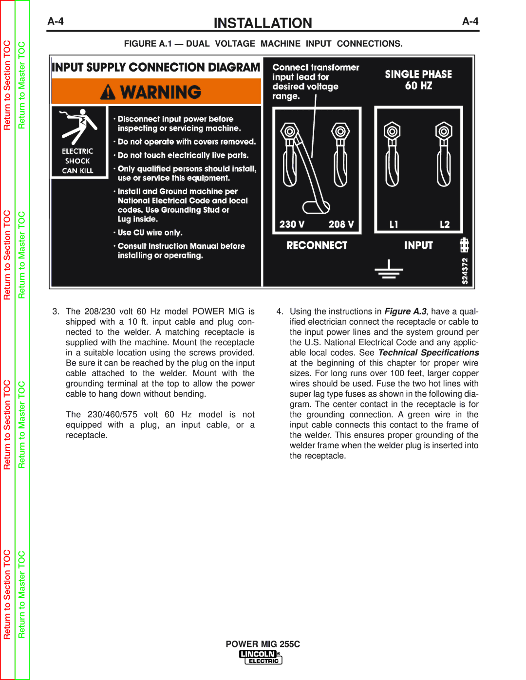
Return to Section TOC | Return to Master TOC | FIGURE A.1 — DUAL VOLTAGE MACHINE INPUT CONNECTIONS. |
|
|
| ||
Return to Section TOC | Return to Master TOC |
|
|
| 3. | The 208/230 volt 60 Hz model POWER MIG is | 4. Using the instructions in Figure A.3, have a qual- |
|
| shipped with a 10 ft. input cable and plug con- | ified electrician connect the receptacle or cable to |
|
| nected to the welder. A matching receptacle is | the input power lines and the system ground per |
|
| supplied with the machine. Mount the receptacle | the U.S. National Electrical Code and any applic- |
|
| in a suitable location using the screws provided. | able local codes. See Technical Specifications |
|
| Be sure it can be reached by the plug on the input | at the beginning of this chapter for proper wire |
TOC |
| cable attached to the welder. Mount with the | sizes. For long runs over 100 feet, larger copper |
TOC | grounding terminal at the top to allow the power | wires should be used. Fuse the two hot lines with | |
cable to hang down without bending. | super lag type fuses as shown in the following dia- | ||
Section | Master | equipped with a plug, an input cable, or a | input cable connects this contact to the frame of |
|
|
| gram. The center contact in the receptacle is for |
|
| The 230/460/575 volt 60 Hz model is not | the grounding connection. A green wire in the |
to | to | receptacle. | the welder. This ensures proper grounding of the |
Return | Return |
| welder frame when the welder plug is inserted into |
| the receptacle. | ||
|
|
|
Return to Section TOC | Return to Master TOC |
POWER MIG 255C