Return to Section TOC
Return to Section TOC
TOC
Return to Master TOC
Return to Master TOC
TOC
| TROUBLESHOOTING AND REPAIR | |
| MAIN TRANSFORMER TEST (continued) |
|
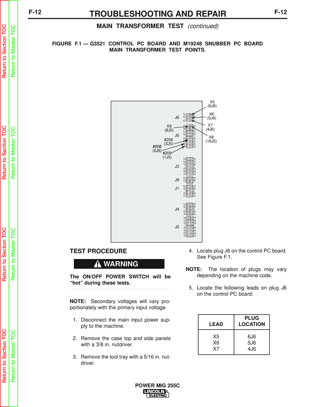
FIGURE F.1 — G3521 CONTROL PC BOARD AND M19248 SNUBBER PC BOARD
MAIN TRANSFORMER TEST POINTS.
|
| X5 |
|
| (6J6) |
| J6 | X6 |
| (5J6) | |
| X9 | X7 |
| (8J5) | (4J6) |
| J5 | X8 |
| #206 | |
| (16J5) | |
| (3J5) | |
#208 |
| |
(2J5) #209 |
| |
| (1J5) |
|
| J3 |
|
| J8 |
|
| J1 |
|
| J4 |
|
| J2 |
|
Return to Section
Return to Section TOC
Return to Master
Return to Master TOC
TEST PROCEDURE
![]() WARNING
WARNING
The ON/OFF POWER SWITCH will be “hot” during these tests.
NOTE: Secondary voltages will vary pro- portionately with the primary input voltage.
1.Disconnect the main input power sup- ply to the machine.
2.Remove the case top and side panels with a 3/8 in. nutdriver.
3.Remove the tool tray with a 5/16 in. nut- driver.
4.Locate plug J6 on the control PC board. See Figure F.1.
NOTE: The location of plugs may vary depending on the machine code.
5.Locate the following leads on plug J6 on the control PC board:
| PLUG |
LEAD | LOCATION |
|
|
X5 | 6J6 |
X6 | 5J6 |
X7 | 4J6 |
|
|
POWER MIG 255C