Return to Section TOC
Return to Section TOC
Return to Master TOC
Return to Master TOC
TROUBLESHOOTING AND REPAIR |
CONTROL BOARD TEST (continued)
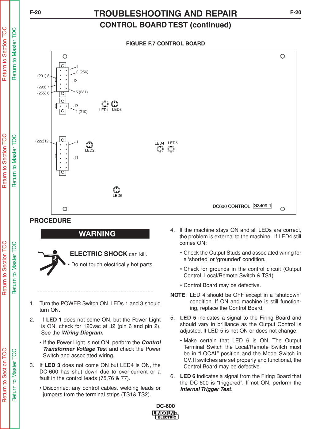
FIGURE F.7 CONTROL BOARD
| 1 |
|
(291) 8 | 2 (256) |
|
J2 |
| |
|
| |
(290) 7 |
|
|
(255) 6 | 5 (231) |
|
|
| |
| J3 | LED1 LED3 |
| 1 (210) | |
|
|
(222)12 | 1 | LED4 | LED5 |
|
|
LED2
J1
LED6
DC600 CONTROL
Return to Section TOC
Return to Section TOC
Return to Master TOC
Return to Master TOC
PROCEDURE
![]() WARNING
WARNING
ELECTRIC SHOCK can kill.
•Do not touch electrically hot parts.
1.Turn the POWER Switch ON. LEDs 1 and 3 should turn ON.
2.If LED 1 does not come ON, but the Power Light is ON, check for 120vac at J2 (pin 6 and pin 2). See the Wiring Diagram.
•If the Power Light is not ON, perform the Control Transformer Voltage Test and check the Power Switch and associated wiring.
3.If LED 3 does not come ON but LED4 is ON, the
•Disconnect any control cables, welding leads or jumpers from the terminal strips (TS1& TS2).
4.If the machine stays ON and all LEDs are correct, the problem is external to the machine. If LED4 still comes ON:
•Check the Output Studs and associated wiring for a ‘shorted’ or ‘grounded’ condition.
•Check for grounds in the control circuit (Output Control, Local/Remote Switch & TS1).
•Control Board may be defective.
NOTE: LED 4 should be OFF except in a “shutdown“ condition. If ON and machine is still function- ing, replace the Control Board.
5.LED 5 indicates a signal to the Firing Board and should vary in brilliance as the Output Control is adjusted. If LED 5 is not ON or does not change:
•Make certain that LED 6 is ON. The Output Terminal Switch the Local/Remote Switch must be in “LOCAL” position and the Mode Switch in CV. If switches are set properly and functional, the Control Board may be defective.
6.LED 6 indicates a signal from the Firing Board that the