THEORY OF OPERATION | ||
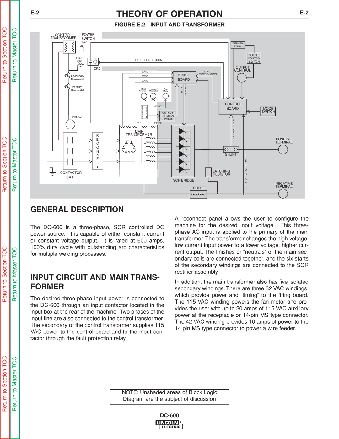
| FIGURE E.2 - INPUT AND TRANSFORMER |
|
Return to Section TOC
Return to Section TOC
CONTROL | POWER |
TRANSFORMER | SWITCH |
115VAC | |
| • |
Pilot |
|
Light | |
w |
|
• | CR2 |
| |
Secondary | |
Thermostat | |
Primary |
|
Theromstat | |
1CR Coil |
|
| R |
| E |
| C |
| O |
| N |
| N |
| E |
| C |
| T |
CONTACTOR
CR1
|
|
|
|
|
|
| TERMINAL |
|
|
|
|
|
|
|
|
| STRIP 1 |
|
|
|
|
|
|
|
|
|
| OUTPUT |
|
FAULT PROTECTION |
|
|
|
|
| CONTROL |
| ||
|
|
|
|
| SWITCH |
| |||
|
|
|
|
|
|
|
|
| |
|
|
|
|
|
|
| OUTPUT |
| |
32VAC |
|
|
|
| OUTPUT | CONTROL |
| ||
32VAC |
|
| FIRING | CONTROL SIGNAL |
|
| |||
|
|
|
|
|
| ||||
32VAC |
|
| BOARD |
|
|
|
| ||
|
|
|
| G | S |
|
|
|
|
115VAC | Fan | A | I |
|
|
|
| ||
T | G |
|
|
|
| ||||
Amphenol | Receptacle | Motor | E | N |
|
|
|
| |
|
|
|
|
| A |
|
|
|
|
|
|
|
|
| L |
|
|
|
|
T |
| 115VAC |
|
|
|
| CONTROL |
|
|
S |
|
|
|
|
|
|
| ||
R | • |
|
|
|
| BOARD |
| MODE | |
T |
|
|
|
|
| ||||
E |
|
| OUTPUT |
|
|
|
|
| SWITCH |
I | I |
|
|
|
|
|
| ||
M | R |
|
|
|
|
|
|
|
|
N | P | TERMINAL |
|
|
|
|
|
| |
AL | 2 |
|
|
|
|
|
| ||
|
|
| SWITCH |
|
|
| F |
|
|
42VAC |
| 115VAC |
|
|
|
| E |
|
|
|
|
|
|
|
|
| E |
|
|
MAIN |
|
|
|
|
|
| D |
|
|
|
|
|
|
|
| B |
|
| |
TRANSFORMER |
|
|
|
| A |
|
| ||
|
|
|
|
|
|
| C |
| POSITIVE |
|
|
|
|
|
|
| K |
| |
|
|
|
|
|
|
|
| TERMINAL | |
|
|
|
|
|
|
|
|
| |
|
|
|
|
|
|
| SHUNT | F |
|
|
|
|
|
|
|
|
|
| |
|
|
|
|
|
|
|
| E |
|
|
|
|
|
|
|
|
| E |
|
|
|
|
|
|
|
| LATCHING | D |
|
|
|
|
|
|
|
|
|
| |
|
|
|
|
|
|
| RESISTOR | B |
|
|
|
|
| SCR BRIDGE |
| A |
| ||
|
|
|
|
| C | NEGATIVE | |||
|
|
|
|
|
|
|
| ||
|
|
|
|
|
| CHOKE |
| K | TERMINAL |
|
|
|
|
|
|
|
| ||
GENERAL DESCRIPTION
Return to Section TOC
Return to Master TOC
Return to Master TOC
Return to Master TOC
The
INPUT CIRCUIT AND MAIN TRANS- FORMER
The desired
A reconnect panel allows the user to configure the machine for the desired input voltage. This three- phase AC input is applied to the primary of the main transformer. The transformer changes the high voltage, low current input power to a lower voltage, higher cur- rent output. The finishes or “neutrals” of the main sec- ondary coils are connected together, and the six starts of the secondary windings are connected to the SCR rectifier assembly.
In addition, the main transformer also has five isolated secondary windings. There are three 32 VAC windings, which provide power and “timing” to the firing board. The 115 VAC winding powers the fan motor and pro- vides the user with up to 20 amps of 115 VAC auxiliary power at the receptacle or
Return to Section TOC
Return to Master TOC
NOTE: Unshaded areas of Block Logic Diagram are the subject of discussion