Return to Section TOC
Return to Section TOC
Return to Master TOC
Return to Master TOC
TROUBLESHOOTING AND REPAIR |
| ||||
| INTERNAL TRIGGER CIRCUIT TEST (continued) |
| |||
|
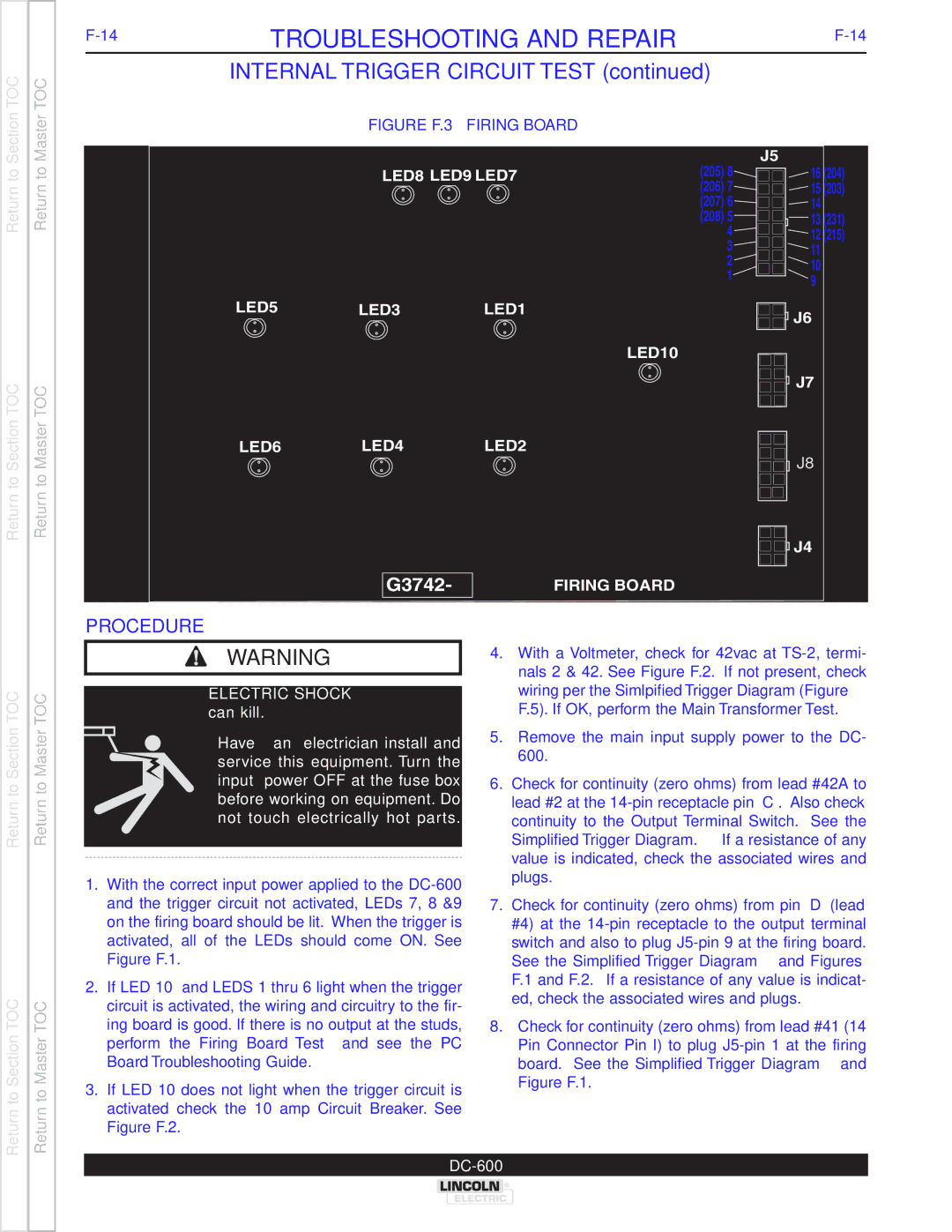
| FIGURE F.3 – FIRING BOARD |
|
| |
|
|
|
| (205) 8 | J5 |
|
| LED8 | LED9 LED7 | 16 (204) | |
|
|
|
| (206) 7 | 15 (203) |
|
|
|
| (207) 6 | 14 |
|
|
|
| (208) 5 | 13 (231) |
|
|
|
| 4 | 12 (215) |
|
|
|
| 3 | 11 |
|
|
|
| 2 | 10 |
|
|
|
| 1 | |
|
|
|
| 9 | |
|
|
|
|
| |
| LED5 | LED3 | LED1 |
| J6 |
|
|
|
|
| |
LED10
J7 |
LED6 LED4 LED2
J8
J4 |
FIRING BOARD |
Return to Section TOC
Return to Section TOC
Return to Master TOC
Return to Master TOC
PROCEDURE
WARNING
ELECTRIC SHOCK can kill.
• Have an electrician install and service this equipment. Turn the input power OFF at the fuse box before working on equipment. Do not touch electrically hot par ts.
1.With the correct input power applied to the
Figure F.1.
2.If LED 10 and LEDS 1 thru 6 light when the trigger circuit is activated, the wiring and circuitry to the fir- ing board is good. If there is no output at the studs, perform the Firing Board Test and see the PC
Board Troubleshooting Guide.
3.If LED 10 does not light when the trigger circuit is activated check the 10 amp Circuit Breaker. See
Figure F.2.
4.With a Voltmeter, check for 42vac at
5.Remove the main input supply power to the DC- 600.
6.Check for continuity (zero ohms) from lead #42A to lead #2 at the
7.Check for continuity (zero ohms) from pin “D” (lead #4) at the
8.Check for continuity (zero ohms) from lead #41 (14 Pin Connector Pin I) to plug