Return to Section TOC
Return to Section TOC
Return to Master TOC
Return to Master TOC
TROUBLESHOOTING AND REPAIR | ||||
MAIN TRANSFORMER VOLTAGE TEST (continued) |
| |||
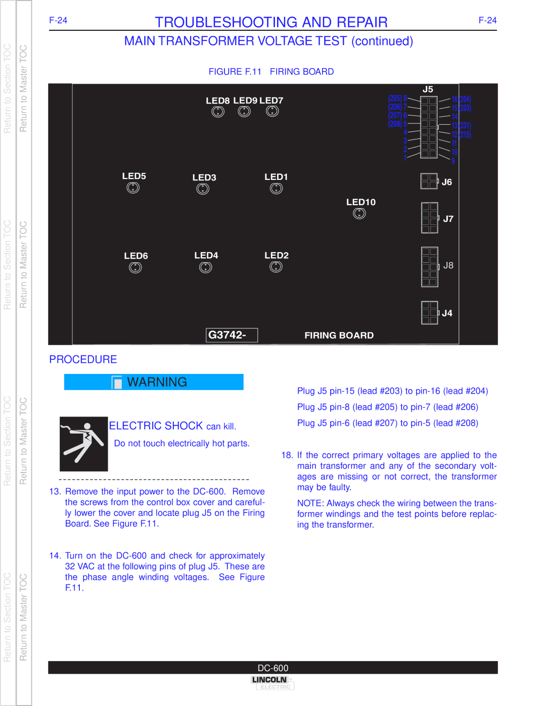
| FIGURE F.11 – FIRING BOARD |
|
| |
|
|
| (205) 8 | J5 |
| LED8 | LED9 LED7 | 16 (204) | |
|
|
| (206) 7 | 15 (203) |
|
|
| (207) 6 | 14 |
|
|
| (208) 5 | 13 (231) |
|
|
| 4 | 12 (215) |
|
|
| 3 | 11 |
|
|
| 2 | 10 |
|
|
| 1 | |
|
|
| 9 | |
|
|
|
| |
LED5 | LED3 | LED1 |
| J6 |
|
|
|
| |
LED10
J7 |
LED6 LED4 LED2
J8
J4 |
FIRING BOARD |
Return to Section TOC
Return to Section TOC
Return to Master TOC
Return to Master TOC
PROCEDURE
![]() WARNING
WARNING
ELECTRIC SHOCK can kill.
•Do not touch electrically hot parts.
13.Remove the input power to the
14.Turn on the
Plug J5
Plug J5
Plug J5
18.If the correct primary voltages are applied to the main transformer and any of the secondary volt- ages are missing or not correct, the transformer may be faulty.
NOTE: Always check the wiring between the trans- former windings and the test points before replac- ing the transformer.