THEORY OF OPERATION | ||
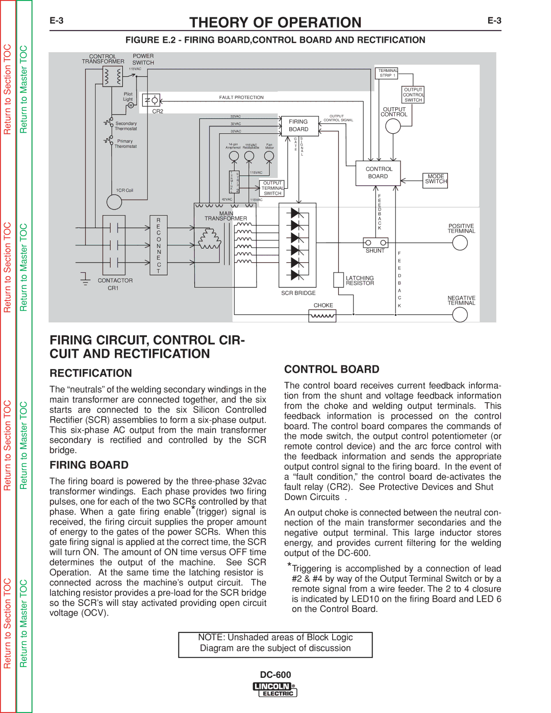
| FIGURE E.2 - FIRING BOARD,CONTROL BOARD AND RECTIFICATION |
|
Return to Section TOC
Return to Section TOC
CONTROL | POWER |
TRANSFORMER | SWITCH |
115VAC | |
| • |
Pilot |
|
Light | |
w |
|
• | CR2 |
| |
Secondary | |
Thermostat | |
Primary |
|
Theromstat | |
1CR Coil |
|
| R |
| E |
| C |
| O |
| N |
| N |
| E |
| C |
| T |
CONTACTOR
CR1
|
|
|
|
|
|
| TERMINAL |
|
|
|
|
|
|
|
|
| STRIP 1 |
|
|
|
|
|
|
|
|
|
| OUTPUT |
|
FAULT PROTECTION |
|
|
|
|
| CONTROL |
| ||
|
|
|
|
| SWITCH |
| |||
|
|
|
|
|
|
|
|
| |
|
|
|
|
|
|
| OUTPUT |
| |
32VAC |
|
|
|
| OUTPUT | CONTROL |
| ||
32VAC |
|
| FIRING | CONTROL SIGNAL |
|
| |||
|
|
|
|
|
| ||||
32VAC |
|
| BOARD |
|
|
|
| ||
|
|
|
| G | S |
|
|
|
|
115VAC | Fan | A | I |
|
|
|
| ||
T | G |
|
|
|
| ||||
Amphenol | Receptacle | Motor | E | N |
|
|
|
| |
|
|
|
|
| A |
|
|
|
|
|
|
|
|
| L |
|
|
|
|
T |
| 115VAC |
|
|
|
| CONTROL |
|
|
S |
|
|
|
|
|
|
| ||
R | • |
|
|
|
| BOARD |
| MODE | |
T |
|
|
|
|
| ||||
E |
|
| OUTPUT |
|
|
|
|
| SWITCH |
I | I |
|
|
|
|
|
| ||
M | R |
|
|
|
|
|
|
|
|
N | P | TERMINAL |
|
|
|
|
|
| |
AL | 2 |
|
|
|
|
|
| ||
|
|
| SWITCH |
|
|
| F |
|
|
42VAC |
| 115VAC |
|
|
|
| E |
|
|
|
|
|
|
|
|
| E |
|
|
MAIN |
|
|
|
|
|
| D |
|
|
|
|
|
|
|
| B |
|
| |
TRANSFORMER |
|
|
|
| A |
|
| ||
|
|
|
|
|
|
| C |
| POSITIVE |
|
|
|
|
|
|
| K |
| |
|
|
|
|
|
|
|
| TERMINAL | |
|
|
|
|
|
|
|
|
| |
|
|
|
|
|
|
| SHUNT | F |
|
|
|
|
|
|
|
|
|
| |
|
|
|
|
|
|
|
| E |
|
|
|
|
|
|
|
|
| E |
|
|
|
|
|
|
|
| LATCHING | D |
|
|
|
|
|
|
|
|
|
| |
|
|
|
|
|
|
| RESISTOR | B |
|
|
|
|
| SCR BRIDGE |
| A |
| ||
|
|
|
|
| C | NEGATIVE | |||
|
|
|
|
|
|
|
| ||
|
|
|
|
|
| CHOKE |
| K | TERMINAL |
|
|
|
|
|
|
|
| ||
Return to Section TOC
Section TOC
Return to Master TOC
Return to Master TOC
Return to Master TOC
Master TOC
FIRING CIRCUIT, CONTROL CIR- CUIT AND RECTIFICATION
RECTIFICATION
The “neutrals” of the welding secondary windings in the main transformer are connected together, and the six starts are connected to the six Silicon Controlled Rectifier (SCR) assemblies to form a
FIRING BOARD
The firing board is powered by the
CONTROL BOARD
The control board receives current feedback informa- tion from the shunt and voltage feedback information from the choke and welding output terminals. This feedback information is processed on the control board. The control board compares the commands of the mode switch, the output control potentiometer (or remote control device) and the arc force control with the feedback information and sends the appropriate output control signal to the firing board. In the event of a “fault condition,” the control board
An output choke is connected between the neutral con- nection of the main transformer secondaries and the negative output terminal. This large inductor stores energy, and provides current filtering for the welding output of the
*Triggering is accomplished by a connection of lead #2 & #4 by way of the Output Terminal Switch or by a remote signal from a wire feeder. The 2 to 4 closure is indicated by LED10 on the firing Board and LED 6 on the Control Board.
Return to
Return to
NOTE: Unshaded areas of Block Logic Diagram are the subject of discussion