THEORY OF OPERATION | ||
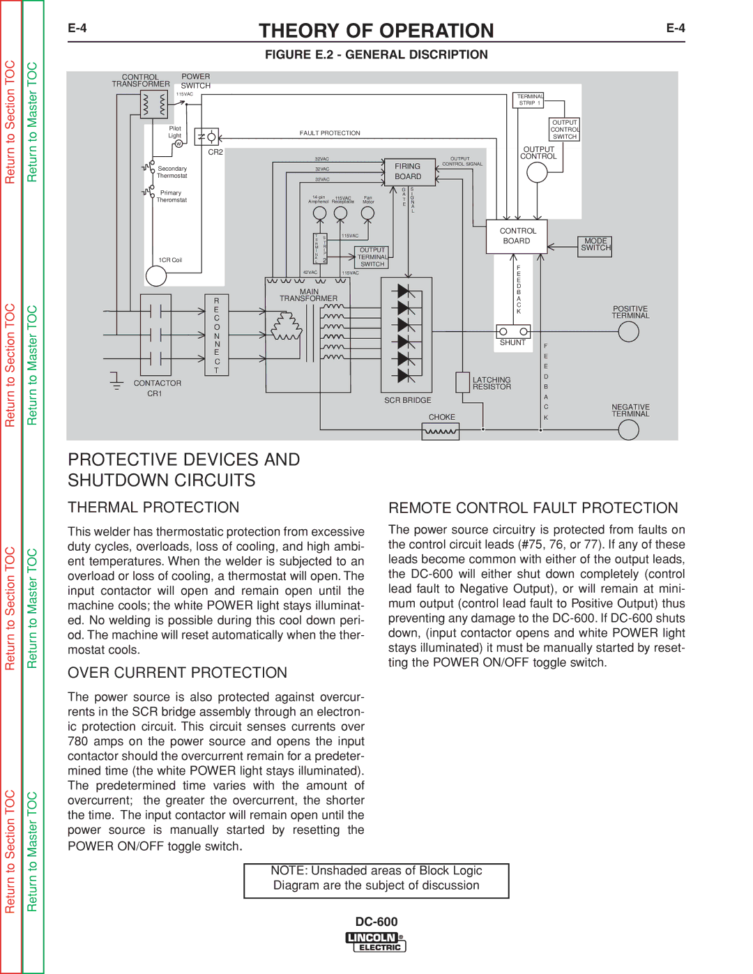
| FIGURE E.2 - GENERAL DISCRIPTION |
|
Return to Section TOC
Return to Section TOC
CONTROL | POWER |
TRANSFORMER | SWITCH |
115VAC | |
| • |
Pilot |
|
Light | |
w |
|
• | CR2 |
| |
Secondary | |
Thermostat | |
Primary |
|
Theromstat | |
1CR Coil |
|
| R |
| E |
| C |
| O |
| N |
| N |
| E |
| C |
| T |
CONTACTOR
CR1
|
|
|
|
|
|
| TERMINAL |
|
|
|
|
|
|
|
|
| STRIP 1 |
|
|
|
|
|
|
|
|
|
| OUTPUT |
|
FAULT PROTECTION |
|
|
|
|
| CONTROL |
| ||
|
|
|
|
| SWITCH |
| |||
|
|
|
|
|
|
|
|
| |
|
|
|
|
|
|
| OUTPUT |
| |
32VAC |
|
|
|
| OUTPUT | CONTROL |
| ||
32VAC |
|
| FIRING | CONTROL SIGNAL |
|
| |||
|
|
|
|
|
| ||||
32VAC |
|
| BOARD |
|
|
|
| ||
|
|
|
| G | S |
|
|
|
|
115VAC | Fan | A | I |
|
|
|
| ||
T | G |
|
|
|
| ||||
Amphenol | Receptacle | Motor | E | N |
|
|
|
| |
|
|
|
|
| A |
|
|
|
|
|
|
|
|
| L |
|
|
|
|
T |
| 115VAC |
|
|
|
| CONTROL |
|
|
S |
|
|
|
|
|
|
| ||
R | • |
|
|
|
| BOARD |
| MODE | |
T |
|
|
|
|
| ||||
E |
|
| OUTPUT |
|
|
|
|
| SWITCH |
I | I |
|
|
|
|
|
| ||
M | R |
|
|
|
|
|
|
|
|
N | P | TERMINAL |
|
|
|
|
|
| |
AL | 2 |
|
|
|
|
|
| ||
|
|
| SWITCH |
|
|
| F |
|
|
42VAC |
| 115VAC |
|
|
|
| E |
|
|
|
|
|
|
|
|
| E |
|
|
MAIN |
|
|
|
|
|
| D |
|
|
|
|
|
|
|
| B |
|
| |
TRANSFORMER |
|
|
|
| A |
|
| ||
|
|
|
|
|
|
| C |
| POSITIVE |
|
|
|
|
|
|
| K |
| |
|
|
|
|
|
|
|
| TERMINAL | |
|
|
|
|
|
|
|
|
| |
|
|
|
|
|
|
| SHUNT | F |
|
|
|
|
|
|
|
|
|
| |
|
|
|
|
|
|
|
| E |
|
|
|
|
|
|
|
|
| E |
|
|
|
|
|
|
|
| LATCHING | D |
|
|
|
|
|
|
|
|
|
| |
|
|
|
|
|
|
| RESISTOR | B |
|
|
|
|
| SCR BRIDGE |
| A |
| ||
|
|
|
|
| C | NEGATIVE | |||
|
|
|
|
|
|
|
| ||
|
|
|
|
|
| CHOKE |
| K | TERMINAL |
|
|
|
|
|
|
|
| ||
Return to Master TOC
Return to Master TOC
PROTECTIVE DEVICES AND
SHUTDOWN CIRCUITS
THERMAL PROTECTION | REMOTE CONTROL FAULT PROTECTION |
Return to Section TOC
Section TOC
Return to Master TOC
Master TOC
This welder has thermostatic protection from excessive duty cycles, overloads, loss of cooling, and high ambi- ent temperatures. When the welder is subjected to an overload or loss of cooling, a thermostat will open. The input contactor will open and remain open until the machine cools; the white POWER light stays illuminat- ed. No welding is possible during this cool down peri- od. The machine will reset automatically when the ther- mostat cools.
OVER CURRENT PROTECTION
The power source is also protected against overcur- rents in the SCR bridge assembly through an electron- ic protection circuit. This circuit senses currents over 780 amps on the power source and opens the input contactor should the overcurrent remain for a predeter- mined time (the white POWER light stays illuminated). The predetermined time varies with the amount of overcurrent; the greater the overcurrent, the shorter the time. The input contactor will remain open until the power source is manually started by resetting the POWER ON/OFF toggle switch.
The power source circuitry is protected from faults on the control circuit leads (#75, 76, or 77). If any of these leads become common with either of the output leads, the
Return to
Return to
NOTE: Unshaded areas of Block Logic Diagram are the subject of discussion