INSTALLATION |
Return to Section TOC
Return to Section TOC
Return to Section TOC
Return to Section TOC
Return to Master TOC
Return to Master TOC
Return to Master TOC
Return to Master TOC
AUXILIARY POWER AND
CONTROL CONNECTIONS
Located at the left side of the front of the welder behind a hinged cover is a 115VAC duplex receptacle for aux- iliary power (60 Hertz Models only). On the right side of the case front is a 14 Pin MS type receptacle for con- nection of auxiliary equipment such as wire feeders. Also, terminal strips with 115VAC and connections for auxiliary equipment are located behind the hinged access panel on the right side of the case front. (see Auxiliary Power Table for details)
AUXILIARY POWER TABLE
Voltage and Circuit Breaker Ratings at Auxiliary Power
Connections for Various Models
Auxiliary | 60 Hz | 50/60 Hz |
Power | Models | Models |
Connections |
|
|
|
|
|
|
|
|
At Duplex | 115V 15A | No Duplex |
Receptacle |
|
|
|
|
|
Terminal strip | 115V 15A | 115V 15A |
terminals 31 & 32 |
|
|
|
|
|
115V 15A | 115V 15A | |
pins A & J |
|
|
|
|
|
42V 10A | 42V 10A | |
pins I & K |
|
|
|
|
|
115VAC DUPLEX RECEPTACLE (60 HERTZ MODELS ONLY)
The 115VAC duplex receptacle is protected by a circuit breaker located on the nameplate. The receptacle is a NEMA
14 PIN MS TYPE RECEPTACLE
(For
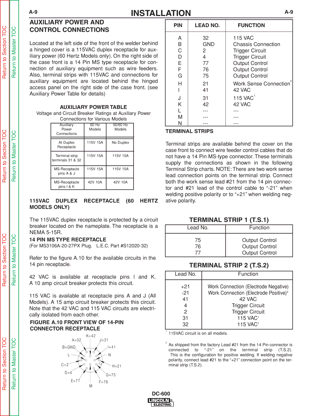
Refer to the figure A.10 for the available circuits in the 14 pin receptacle.
42 VAC is available at receptacle pins I and K. A 10 amp circuit breaker protects this circuit.
115 VAC is available at receptacle pins A and J (All Models). A 15 amp circuit breaker protects this circuit. Note that the 42 VAC and 115 VAC circuits are electri- cally isolated from each other.
FIGURE A.10 FRONT VIEW OF 14-PIN
CONNECTOR RECEPTACLE
| K = 4 2 |
A = 3 2 | J = 3 1 |
B = G N D | I = 4 1 |
L | N |
C = 2 | H = 2 1 |
| |
D = 4 | G = 7 5 |
| |
E = 7 7 | F = 7 6 |
| |
| M |
PIN | LEAD NO. | FUNCTION |
|
|
|
A | 32 | 115 VAC |
B | GND | Chassis Connection |
C | 2 | Trigger Circuit |
D | 4 | Trigger Circuit |
E | 77 | Output Control |
F | 76 | Output Control |
G | 75 | Output Control |
H | 21 | Work Sense Connection2 |
I | 41 | 42 VAC |
J | 31 | 115 VAC1. |
K | 42 | 42 VAC |
L | ||
M | ||
N |
TERMINAL STRIPS
Terminal strips are available behind the cover on the case front to connect wire feeder control cables that do not have a 14 Pin
TERMINAL STRIP 1 (T.S.1)
Lead No. | Function |
|
|
75 | Output Control |
76 | Output Control |
77 | Output Control |
|
|
TERMINAL STRIP 2 (T.S.2)
Lead No. | Function |
|
|
+21 | Work Connection (Electrode Negative) |
Work Connection (Electrode Positive)2 | |
41 | 42 VAC |
4 | Trigger Circuit |
2 | Trigger Circuit |
31 | 115 VAC1 |
32 | 115 VAC1 |
|
|
1.115VAC circuit is on all models.
2.As shipped from the factory Lead #21 from the 14 Pin connector is
connected to