Lincoln Electric SVM188-A service manual Figure C.2 MULTI-PROCESS Switch Cable Connections

Models: SVM188-A

1 97
Download 97 pages 32.48 Kb
Page 31
Image 31

C-3

ACCESSORIES

C-3

Return to Section TOC

Section TOC

The MULTI-PROCESS SWITCH has two sets of output terminals. You connect the wire feeder unit cables to the set of terminals on the left side of the box and the stick or air/carbon arc cables to the set of terminals on the right side (facing the front of the machine) as shown in Figure C.1. The output terminals are protect- ed against accidental contact by hinged covers.

When the MULTI-PROCESS SWITCH is in the "Stick or Air/Carbon Arc" position, only those terminals are energized. The wire feeder nozzle or gun and electrode are not electrically "hot" when in this mode.

Follow these steps to install the MULTI-PROCESS SWITCH:

1.Confirm that the DC-600 POWER ON/OFF switch is in the OFF position.

2.Disconnect main AC input power to the DC-600.

TERMINAL

STRIP COVER

BOX

CONNECTOR

21+

21- 41

4

2

31 32

75 76 77


CONTROL


LEADS

NEGATIVE (–)


+

POSITIVE (+)

OUTPUT


OUTPUT

STUD


STUD

ELECTRODE

ELECTRODE

CABLE

CABLE

WIRE

WORK

+

STICK AIR/CARBON


ARC WELDING

FEEDER


EQUIPMENT


ELECTRODES


WORK


WORK

CABLE

JUMPER (IF NEEDED

CABLE


SEE INSTRUCTIONS)


Return to

Return to Section TOC

Return to Section TOC

Return to Master TOC

Return to Master TOC

Return to Master TOC

Return to Master TOC

3.Open the terminal strip hinged cover located on the Case Front Assembly.

4.The MULTI-PROCESS SWITCH is mounted to the case front with four 1/4” self-tapping screws. The screw holes are 13.8” apart side to side and 4.5” apart top to bottom, Run one of the 1/4” screws part way in and out of the screw holes to open them up. Make sure that the two sleeved control leads do not get pinched when hanging the switch; route them out the side to the right of the switch. Support the switch in position and start the four screws, then tighten them.

5.Route the MULTI-PROCESS SWITCH control leads through the strain-relief box connectors and into the terminal strip. Connect wire feeder control cable as specified in specific connection diagram and make other terminal strip connections as specified on the connection diagram for the Lincoln wire feeder being used.

6.Connect the control leads from the MULTI- PROCESS SWITCH to terminals #2 and #4 on the DC-600's terminal strip.

7.Connect the right cable from the MULTI- PROCESS SWITCH (facing the front of the machine) to the DC-600 positive (+) output termi- nal. See Figure C.2.

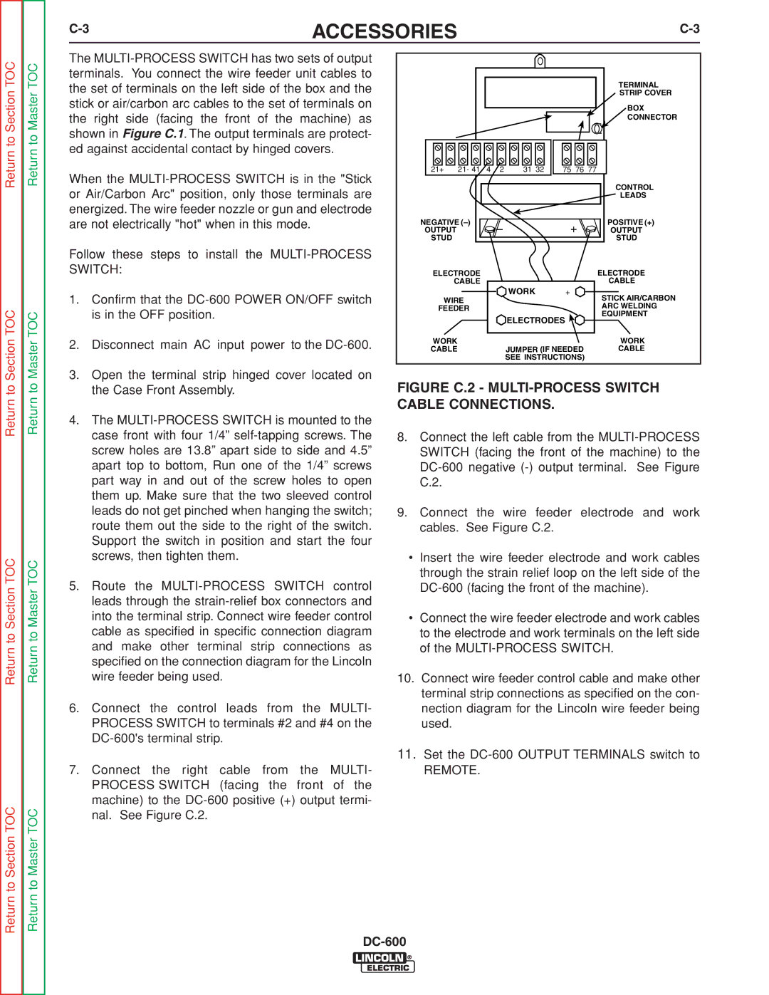
FIGURE C.2 - MULTI-PROCESS SWITCH CABLE CONNECTIONS.

8.Connect the left cable from the MULTI-PROCESS SWITCH (facing the front of the machine) to the DC-600 negative (-) output terminal. See Figure C.2.

9.Connect the wire feeder electrode and work cables. See Figure C.2.

Insert the wire feeder electrode and work cables through the strain relief loop on the left side of the DC-600 (facing the front of the machine).

Connect the wire feeder electrode and work cables to the electrode and work terminals on the left side of the MULTI-PROCESS SWITCH.

10.Connect wire feeder control cable and make other terminal strip connections as specified on the con- nection diagram for the Lincoln wire feeder being used.

11.Set the DC-600 OUTPUT TERMINALS switch to

REMOTE.

DC-600

Page 31
Image 31
Lincoln Electric SVM188-A service manual Figure C.2 MULTI-PROCESS Switch Cable Connections