Return to Section TOC
Return to Section TOC
Return to Master TOC
Return to Master TOC
TROUBLESHOOTING AND REPAIR |
SCR BRIDGE TEST(continued)
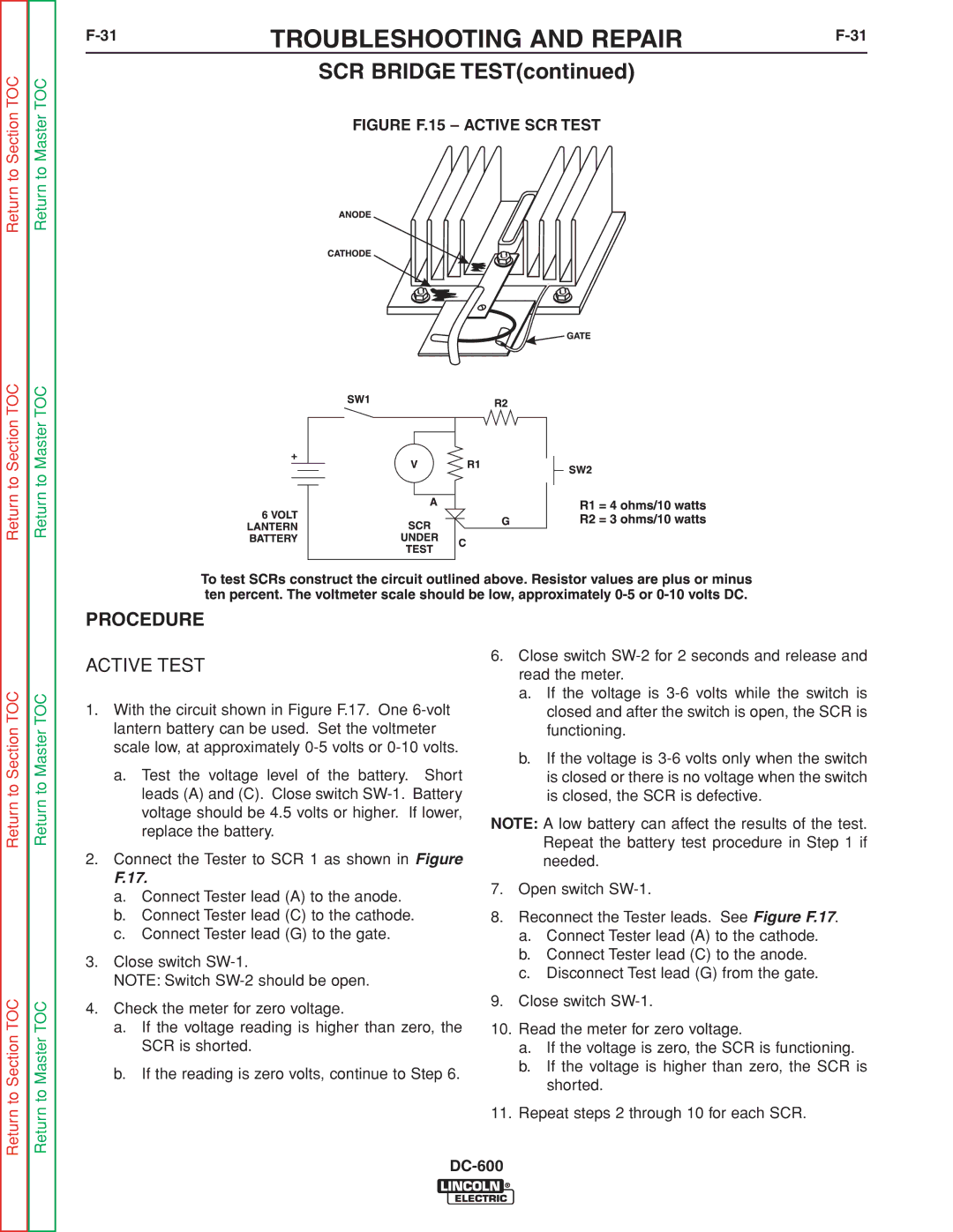
FIGURE F.15 – ACTIVE SCR TEST
PROCEDURE
Return to Section TOC
Return to Section TOC
Return to Master TOC
Return to Master TOC
ACTIVE TEST
1.With the circuit shown in Figure F.17. One
a.Test the voltage level of the battery. Short leads (A) and (C). Close switch
2.Connect the Tester to SCR 1 as shown in Figure
F.17.
a.Connect Tester lead (A) to the anode.
b.Connect Tester lead (C) to the cathode.
c.Connect Tester lead (G) to the gate.
3.Close switch
NOTE: Switch
4.Check the meter for zero voltage.
a.If the voltage reading is higher than zero, the SCR is shorted.
b.If the reading is zero volts, continue to Step 6.
6.Close switch
a.If the voltage is
b.If the voltage is
NOTE: A low battery can affect the results of the test. Repeat the battery test procedure in Step 1 if needed.
7.Open switch
8.Reconnect the Tester leads. See Figure F.17.
a.Connect Tester lead (A) to the cathode.
b.Connect Tester lead (C) to the anode.
c.Disconnect Test lead (G) from the gate.
9.Close switch
10.Read the meter for zero voltage.
a.If the voltage is zero, the SCR is functioning.
b.If the voltage is higher than zero, the SCR is shorted.
11.Repeat steps 2 through 10 for each SCR.