Return to Section TOC
Return to Section TOC
Return to Master TOC
Return to Master TOC
| TROUBLESHOOTING AND REPAIR | ||
| PC BOARD TROUBLESHOOTING GUIDE (continued) |
| |
|
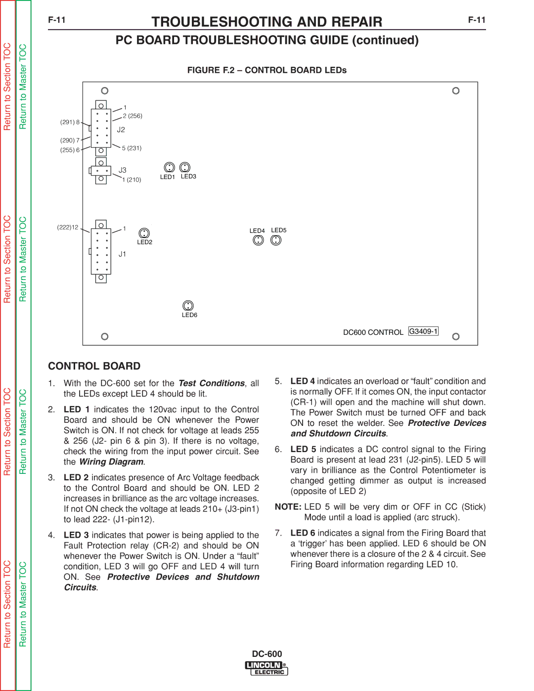
| FIGURE F.2 – CONTROL BOARD LEDs |
|
| 1 |
|
|
(291) 8 | 2 (256) |
|
|
J2 |
|
| |
|
|
| |
(290) 7 |
|
|
|
(255) 6 | 5 (231) |
|
|
|
|
| |
| J3 | LED1 LED3 |
|
| 1 (210) |
| |
|
|
| |
(222)12 | 1 | LED4 | LED5 |
|
|
LED2
J1
LED6
DC600 CONTROL
Return to Section TOC
Return to Section TOC
Return to Master TOC
Return to Master TOC
CONTROL BOARD
1.With the
2.LED 1 indicates the 120vac input to the Control Board and should be ON whenever the Power Switch is ON. If not check for voltage at leads 255 & 256 (J2- pin 6 & pin 3). If there is no voltage, check the wiring from the input power circuit. See the Wiring Diagram.
3.LED 2 indicates presence of Arc Voltage feedback to the Control Board and should be ON. LED 2 increases in brilliance as the arc voltage increases. If not ON check the voltage at leads 210+
4.LED 3 indicates that power is being applied to the Fault Protection relay
5.LED 4 indicates an overload or “fault” condition and is normally OFF. If it comes ON, the input contactor
6.LED 5 indicates a DC control signal to the Firing Board is present at lead 231
NOTE: LED 5 will be very dim or OFF in CC (Stick) Mode until a load is applied (arc struck).
7.LED 6 indicates a signal from the Firing Board that a ‘trigger’ has been applied. LED 6 should be ON whenever there is a closure of the 2 & 4 circuit. See Firing Board information regarding LED 10.