Return to Section TOC
Return to Master TOC
TROUBLESHOOTING AND REPAIR |
MAIN TRANSFORMER AND CHOKE
REMOVAL AND REPLACEMENT (continued)
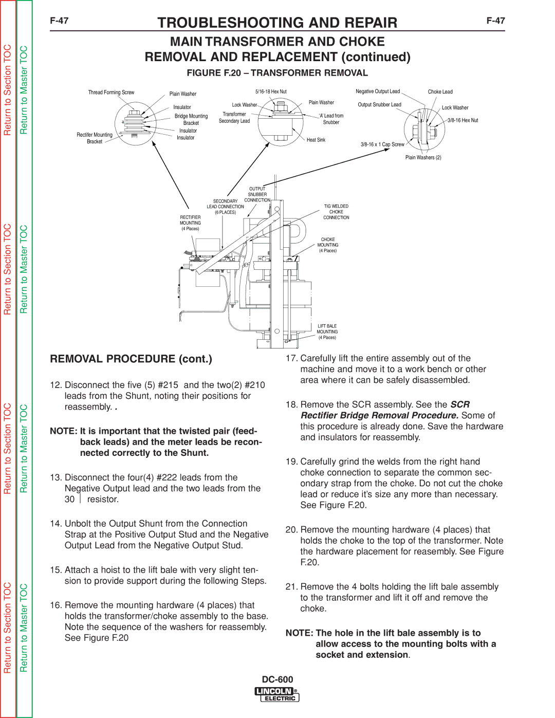
FIGURE F.20 – TRANSFORMER REMOVAL
Thread Forming Screw | Plain Washer | Negative Output Lead | Choke Lead | |
|
|
|
|
| Insulator | Lock Washer | Plain Washer | Output Snubber Lead | Lock Washer |
|
| ||||
| Transformer |
|
| ||
| Bridge Mounting | ‘A’ Lead from |
| ||
| Secondary Lead |
| |||
| Bracket | Snubber |
| ||
|
|
|
| ||
Rectifer Mounting | Insulator |
|
|
|
|
Insulator |
| Heat Sink |
|
| |
Bracket |
|
|
| ||
|
|
| |||
|
|
|
|
| |
|
|
|
|
| Plain Washers (2) |
Return to Section TOC
Return to Master TOC
| OUTPUT | |
| SNUBBER | |
SECONDARY | CONNECTION | |
LEAD CONNECTION | A | |
|
| A |
(6 PLACES) |
|
|
|
| |
|
| |
RECTIFIER MOUNTING (4 Places)
A
A
A ![]()
![]()
A |
A
A
A
TIG WELDED
CHOKE
CONNECTION
CHOKE
MOUNTING
(4 Places)
A
LIFT BALE
MOUNTING
(4 Places)
Return to Section TOC
Return to Section TOC
Return to Master TOC
Return to Master TOC
REMOVAL PROCEDURE (cont.)
12.Disconnect the five (5) #215 and the two(2) #210 leads from the Shunt, noting their positions for reassembly. .
NOTE: It is important that the twisted pair (feed- back leads) and the meter leads be recon- nected correctly to the Shunt.
13.Disconnect the four(4) #222 leads from the
Negative Output lead and the two leads from the 30 ⏐ resistor.
14.Unbolt the Output Shunt from the Connection Strap at the Positive Output Stud and the Negative Output Lead from the Negative Output Stud.
15.Attach a hoist to the lift bale with very slight ten- sion to provide support during the following Steps.
16.Remove the mounting hardware (4 places) that holds the transformer/choke assembly to the base. Note the sequence of the washers for reassembly. See Figure F.20
17.Carefully lift the entire assembly out of the machine and move it to a work bench or other area where it can be safely disassembled.
18.Remove the SCR assembly. See the SCR Rectifier Bridge Removal Procedure. Some of this procedure is already done. Save the hardware and insulators for reassembly.
19.Carefully grind the welds from the right hand choke connection to separate the common sec- ondary strap from the choke. Do not cut the choke lead or reduce it’s size any more than necessary. See Figure F.20.
20.Remove the mounting hardware (4 places) that holds the choke to the top of the transformer. Note the hardware placement for reasembly. See Figure F.20.
21.Remove the 4 bolts holding the lift bale assembly to the transformer and lift it off and remove the choke.
NOTE: The hole in the lift bale assembly is to allow access to the mounting bolts with a socket and extension.