SECURE CONSOLE SERVERS

Connecting to the SCS

2.3 Connecting to the SCS

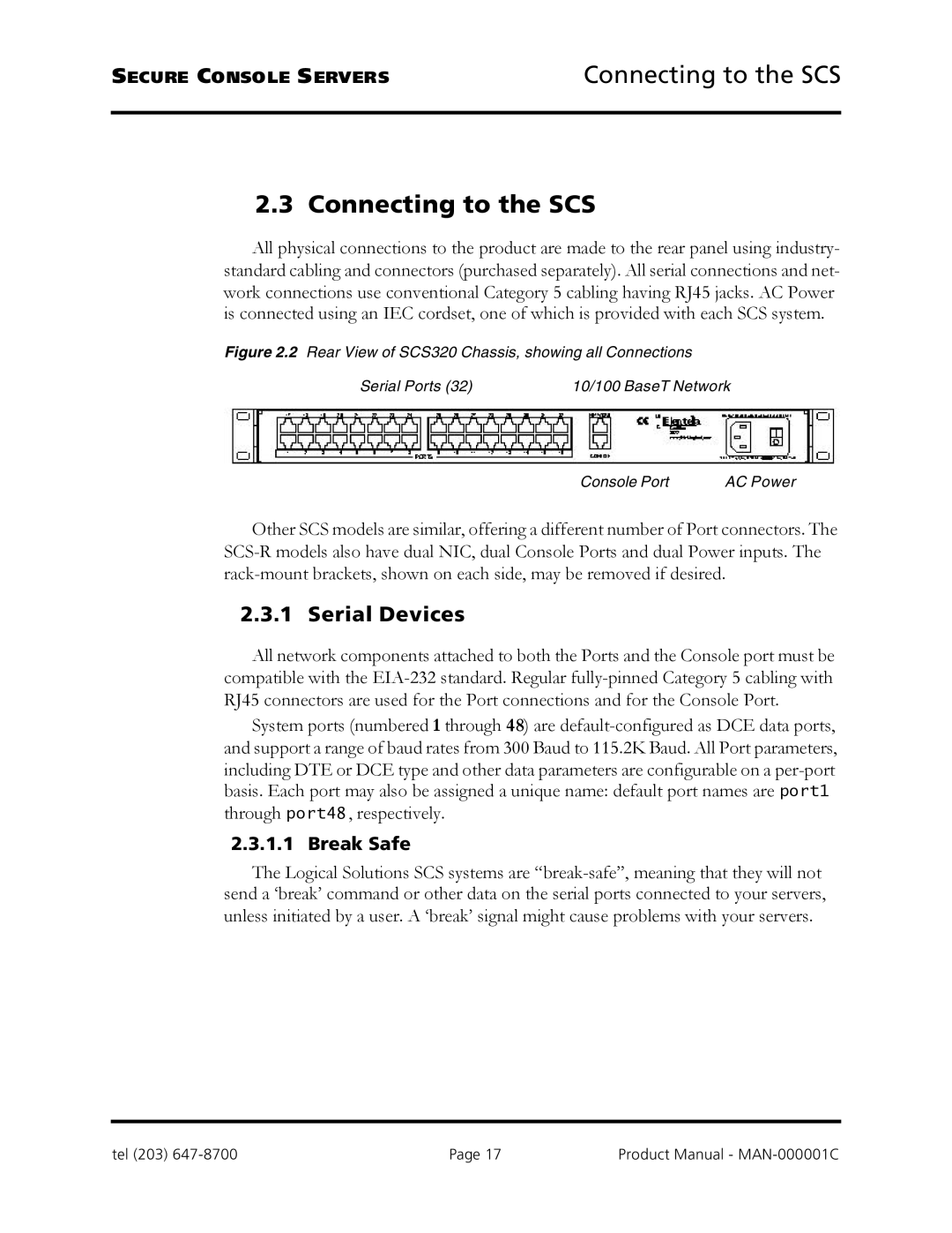
All physical connections to the product are made to the rear panel using industry- standard cabling and connectors (purchased separately). All serial connections and net- work connections use conventional Category 5 cabling having RJ45 jacks. AC Power is connected using an IEC cordset, one of which is provided with each SCS system.

Figure 2.2 Rear View of SCS320 Chassis, showing all Connections

Serial Ports (32)

10/100 BaseT Network

Console Port

AC Power

Other SCS models are similar, offering a different number of Port connectors. The SCS-R models also have dual NIC, dual Console Ports and dual Power inputs. The rack-mount brackets, shown on each side, may be removed if desired.

2.3.1 Serial Devices

All network components attached to both the Ports and the Console port must be compatible with the EIA-232 standard. Regular fully-pinned Category 5 cabling with RJ45 connectors are used for the Port connections and for the Console Port.

System ports (numbered 1 through 48) are default-configured as DCE data ports, and support a range of baud rates from 300 Baud to 115.2K Baud. All Port parameters, including DTE or DCE type and other data parameters are configurable on a per-port basis. Each port may also be assigned a unique name: default port names are port1 through port48 , respectively.

2.3.1.1 Break Safe

The Logical Solutions SCS systems are “break-safe”, meaning that they will not send a ‘break’ command or other data on the serial ports connected to your servers, unless initiated by a user. A ‘break’ signal might cause problems with your servers.

tel (203) 647-8700

Page 17

Product Manual - MAN-000001C

Page 17
Image 17
Logical Solutions SCS-R manual Connecting to the SCS, Serial Devices, Break Safe