Overview Installation Troubleshooting Contact FAQ Specifications Glossary License
Configuration: Basic Gateway TCP/IP Wireless Print Server USB
Use M5 x 38 mm
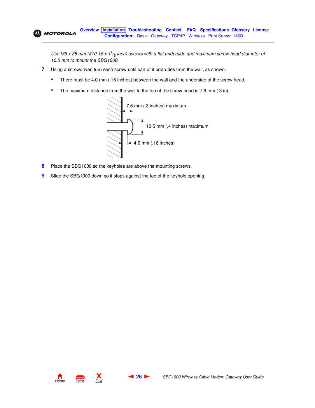
7Using a screwdriver, turn each screw until part of it protrudes from the wall, as shown:
•
•
There must be 4.0 mm (.16 inches) between the wall and the underside of the screw head.
The maximum distance from the wall to the top of the screw head is 7.6 mm (.3 in).
7.6mm (.3 inches) maximum
10.5mm (.4 inches) maximum
4.0mm (.16 inches)
8Place the SBG1000 so the keyholes are above the mounting screws.
9Slide the SBG1000 down so it stops against the top of the keyhole opening.
X | 26 | SBG1000 Wireless Cable Modem Gateway User Guide |