5 E1 Daughter Card
E1 Facility Termination
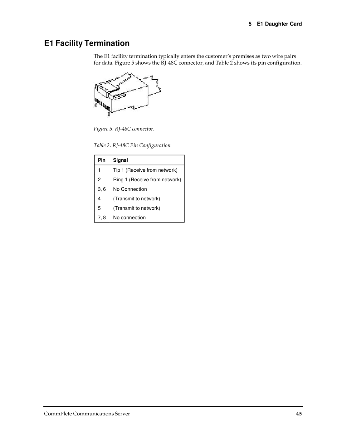
The E1 facility termination typically enters the customer’s premises as two wire pairs for data. Figure 5 shows the
Figure 5. RJ-48C connector.
Table 2. RJ-48C Pin Configuration
Pin Signal
1Tip 1 (Receive from network)
2Ring 1 (Receive from network) 3, 6 No Connection
4(Transmit to network)
5(Transmit to network) 7, 8 No connection
CommPlete Communications Server | 45 |