Model DCA-600SSK
Diesel engine exhaust and some
Proposition 65WARNING
DCA-600SSK Operation and Parts Manual STD- REV. #7 04/30/10
Table of Contents
Ordering parts has never been easier
Parts Ordering Procedures
DCA-600SSK Specifications
DCA-600SSK Operation and Parts Manual STD- REV. #7 04/30/10
Dimensions
DCA-600SSK Dimensions TOP and Side
DCA-600SSK Dimensions Front , Rear and Doors
Hazard Symbols
DCA-600SSK Safety Message Alert Symbols
This generator, other property
DCA-600SSK Safety Message Alert Symbols
Burns
General Safety
Generator Grounding
Electrical Safety
DCA-600SSK Rules for Safe Operation
Battery Safety
Maintenance Safety
Emergencies
Towing & Transporting Safety
DCA-600SSK Rules for Safe Operation
Typical Generator Grounding Application
DCA-600SSK Installation
Mounting
DCA-600SSK Installation
Outdoor Installation
DCA-600SSK -TOWING Rules for Safe Operation
Towing Safety Precautions
Coupler Type of hitch used on the trailer for towing
DCA-600SSK TRAILER-SAFETY Guidelines
Explanation of Chart
DCA-600SSK -TRAILER-SPECIFICATIONS
Specifications
DCA-600SSK -TRAILER-SPECIFICATIONS
Machine Safety Decals
DCA-600SSK Operation and Safety Decals
DCA-600SSK Operation and Safety Decals
DCA-600SSK Operation and Safety Decals
DCA-600SSK Operation and Safety Decals
DCA-600SSK General Information
Generator Major Components
DCA-600SSK Major Components
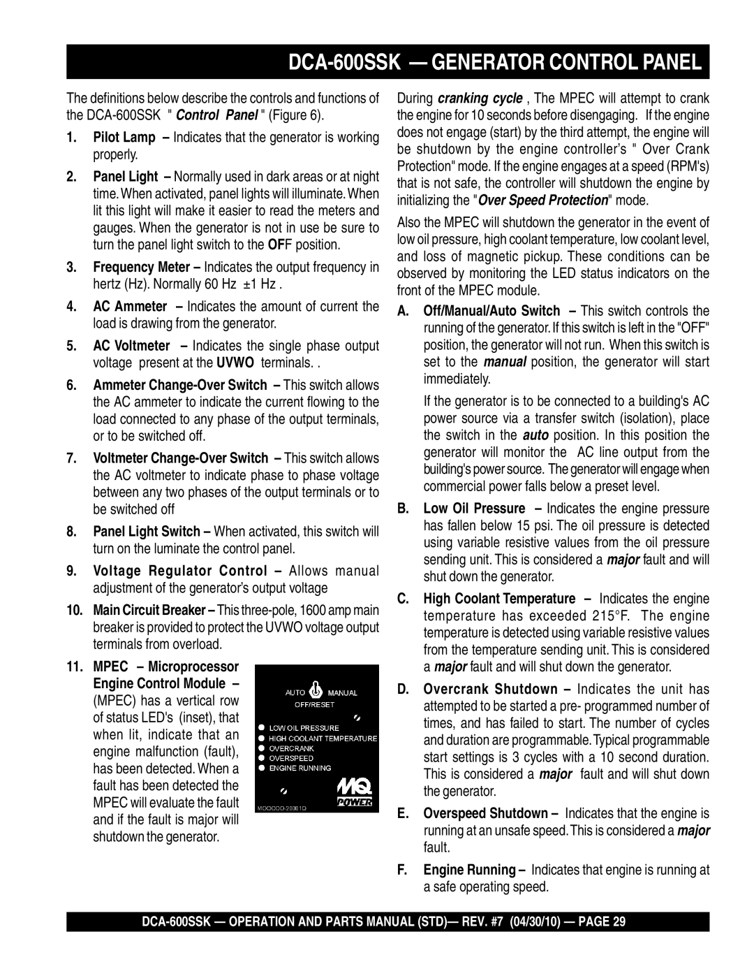
Generator Control Panel
DCA-600SSK Generator Control Panel
Pilot Lamp Indicates that the generator is working properly
DCA-600SSK Generator Control Panel
Engine Operating Panels
DCA-600SSK Engine Operating Panel
Fuel Level Gauge Indicates amount of diesel fuel remaining
Output Terminal Panel
Output Terminal Familiarization
120VAC Gfci Receptacles
Access to Uvwo Terminals
DCA-600SSK Output Terminal Panel Overview
Maximum Power Output KW
Connecting Loads
DCA-600SSK Output Terminal Panel Overview
Over Current Relay
DCA-600SSK- Load Application
Single Phase Load
Three Phase Load
Voltage Change-Over Board
Generator OutputVoltages
Generator Amperage
240V 480V
Maximum Amps
How to Read the Output Terminal Gauge
DCA-600SSK Generator OUTPUTS/GAUGE Reading
Uvwo Terminal Output Voltages
DCA-600SSK Output Terminal Panel Connections
3Ø-240V Uvwo Terminal Output Voltages
1Ø-240V Uvwo Terminal Output Voltages
3Ø-480V Uvwo Terminal Output Voltages
DCA-600SSK Output Terminal Panel Connections
1Ø-480V Uvwo Terminal Output Voltages
1Ø-277V Uvwo Terminal Output Voltages
Lubrication Oil
DCA-600SSK PRE-SETUP
Circuit Breakers
Fuel from the secondary inner
Refueling Procedure
Refueling
Full Trailer Tank
Cleaning the Radiator
DCA-600SSK- PRE-SETUP
Air Cleaner Fan Belt Tension
Operation Freezing Weather
Battery Cable Installation
Battery
Wiring
Alternator
Engines exhaust contains harmful emissions
DCA-600SSK GEN. START-UP Procedure Manual
If applicable perform the following
Generator and Control Panel
Set the battery ON/OFF switch to the on position
DCA-600SSK- Generator START-UP Procedure Manual
Oil Pressure Gauge
DCA-600SSK- Generator START-UP Procedure Manual
Pre-Heat Button Lamp
DCA-600SSK Generator START-UP Procedure Manual
Set the engine speed switch to the High position
DCA-600SSK Generator START-UP Procedure Auto Mode
Engine Shutdown Controller S/N 3698617~
DCA-600SSK Generator SHUT-DOWN Procedure
Emergency Shutdown Procedure
Inspection / Maintenance
DCA-600SSK Maintenance
Service Daily
Air Cleaner
Cleaning the Fuel Strainer
General Inspection
Replacing Fuel Filter
Flushing Out Radiator and Changing Coolant
Changing Oil
Greasing
Cleaning Breather Element
Generator Storage
Removal From Long Term Storage
Battery Charger/Jacket Water Heater Power Connections
DCA-600SSK -TRAILER Brakes Maintenance
Tires/Wheels/Lug Nuts
DCA-600SSK -TRAILER Maintenance
Tire Wear/Inflation
Suspension
Lug Nut Torque Requirements
DCA-600SSK -TRAILER Maintenance
Start all wheel lug nuts by hand
Lug nuts
Trailer Wiring Diagram 5-Pin
DCA-600SSK -TRAILER-WIRING Diagram
DCA-600SSK -TRAILER-WIRING Diagram
Generator Wiring Diagram
DCA-600SSK -GENERATORWIRING Diagram
Main Circuit Breaker Wiring Diagram
DCA-600SSK Generator Wiring Diagram Main Breaker
Engine Wiring Diagram
DCA-600SSK Engine Wiring Diagram
DCA-600SSK Engine Wiring Diagram
Electronic Governor Controller
DCA-600SSK Electronic GOV. Controller Wiring Diagram
Starter does not run
Engine does not start
Engine revolution is not
DCA-600SSK -TROUBLESHOOTING Engine
Smooth
Deficient output
Generator Troubleshooting
DCA-600SSK -TROUBLESHOOTING GENERATOR/ENGINE
Engine Controller Troubleshooting Mpec
DCA-600SSK -TROUBLESHOOTING Mpec
Xxxxx only Not Used on
Explanation of Code in Remarks Column
Qty Description
DCA-600SSK Suggested Spare Parts
DCA-600SSK w/SA6D170AE-1 Komatsu Engine
Generator Assy
DCA-600SSK Generator Assy
Field Assy
Balancing Weight KIT
Insulator Washer
FAN
DCA-600SSK Generator Assy
Plain Washer
Grommet
COVER, Bearing
GASKET, Bearing
Control BOX Assy
DCA-600SSK Control BOX Assy
Bracket
Over Current Relay
Fuse Left Side 5A
Fuse 30A
DCA-600SSK Control BOX Assy
Terminal Plate
Change Terminal
Change Plate
WASHER, Lock
DCA-600SSK Control BOX Assy
DCA-600SSK Control BOX ASSY. S/N 3692433 and below
DCA-600SSK Control BOX Assy
Speed Sensor
Engine & Radiator Assy
DCA-600SSK Engine & Radiator Assy
Engine Foot
Include Item W
BRACKET, Radiator
DCA-600SSK Engine & Radiator Assy
AIR Cleaner Connector
AIR Cleaner Assy
GASKET, AC Connector
Bushing
Engine Operating Panel Assy
DCA-600SSK Engine Operating Panel Assy
STAY, Battery Switch
SET PLATE, Battery Switch
Support LEG
Rubber Cover
Output Terminal Assy
DCA-600SSK Outputterminal Assy
BRACKET, Output Terminal
Output Terminal
Terminal
COVER, Output Terminal
DCA-600SSK Outputterminal Assy
Cover
Stopper
Battery Assy
DCA-600SSK Battery Assy
Battery Sheet
Battery
Battery Band
Battery Bolt
Muffler Assy
DCA-600SSK Muffler Assy
Exhaust Pipe
Muffler
Outlet Pipe
Gasket
Fuel Tank Assy
DCA-600SSK Fueltank Assy
Tank Band
HOSE, Fuel Gauge
PAD, Tank Band
Tank Sheet
Enclosure #1 Assy
DCA-600SSK Enclosure #1 Assy
Part Name QTY Remarks
Enclosure #2 Assy
DCA-600SSK Enclosure #2 Assy
Louver Panel
Rear Frame
COVER, Rear Frame
Lining
DCA-600SSK Enclosure #2 Assy
Emblem
CAP
Roof Panel
Guide
Enclosure #3 Assy
DCA-600SSK Enclosure #3 Assy
Side Door
Side Panel
Duct
Hinge
Rubber Seal Assy
DCA-600SSK Rubber Seal Assy
0228900970
0228901640
0228901100
0228900990
Name Plate and Decals
DCA-600SSK Nameplate and Decals
Z011000130
Decal DROOP, Z011000120
Z011000150
0800520100
DCA-600SSK Nameplate and Decals
Decal Handling Procedures
Procedure Group
Decal 3-PHASE Output Terminal
Decal Water Drain Cock
Freightpolicy
Terms and Conditions of Sale Parts
DCA-600SSK Operation and Parts Manual STD- REV. #7 04/30/10
HERE’S HOW to GET Help