CVX 600 Multi-Service Access Switch
Page
A. Requirements
FCC Radio Frequency Notice for the CVX 600 Access Switch
Interface Service Code Facility Code
FCC Part 68 General Information
Canadian Requirements
FCC and Telephone Company Procedures and Requirements
Australian Requirements
UL Listing and CSA Certification U.S. and Canada
EMI/EN 55 022 Statement
European Requirements
Canada CS-03 Rè gles et rè glements
EC Declaration of Conformity
Voluntary Control Council for Interference Vcci Statement
Japan/Nippon Requirements Only
Jate Requirements
DC Power Supply Warnings
General Warnings
Lithium Battery Caution
Contents
Chapter Chassis Installation
Chapter Chassis Connections
Connecting Chassis to an AC Power Source
Chapter Replacing CVX 600 Components
Appendix a Technical Specifications
Tool and Parts Needed
Page
Topics
About This Guide
Introduction
This preface covers the following topics
Chapters and Appendixes in This Guide
This guide contains the following chapters and appendixes
Information About CVX Products
Accessing Related Documentation
Accessing Software Upgrades
About This Release
Technical Support
Customer Services
Equipment Problems
Product Damage
About This Chapter
This chapter describes how to install the CVX 600 chassis
This chapter covers the following topics
CVX 600 Chassis Overview
Remote Access Configuration
Where to Install
Description
Front View of CVX 600 Chassis
Following figure shows the front of the CVX 600 chassis
Rear View of CVX 600 Chassis
Following figure shows the rear of the CVX 600 chassis
Reference
Preparing the Site for the Installation
Overview
Mounting Options
Ft Telco rack Surface mounted
Rack Capacity
Rack Placement
Mounting the CVX 600 in a Rack
Rack Requirements
Nortel Networks PTE 2000 Rack
Size and Weight Considerations
Ceiling Requirements
Properly ventilated Well lighted
Anchor Kits
Reference
Kit Number Earthquake Zone Floor Type Compliance
Flooring Requirements
Following table lists the PTE 2000 racks and dimensions
Space Requirements
Depth for Drilling
Access Considerations
Rack Cooling Requirements
CVX 600 uses either an AC or DC power source
AC and DC Power
AC Power Option
DC Power Option
Unpacking the Shipment
Preparing for the CVX 600 Installation
Step Action
Checking the Shipment
Tools
Service Console
Tools and Equipment Needed
Cables and Cable Ties
Mounting Hardware
Installing the CVX 600 Chassis
Positioning the Chassis on a Flat Surface
Installing the Feet on the Bottom of the Chassis
To install the feet, follow these steps
Mounting flanges are preinstalled on the chassis
Mounting the Chassis in a Rack
Telco and EIA Rack Hole Spacing
Hardware Needed to Complete the Chassis Installation
Installing the Chassis
To install the chassis, follow these steps
Use a Phillips screwdriver to tighten the screws
Chapter Chassis Connections
Alarm Categories
Connecting Alarms
Alarm Possible Cause
Alarm Types
Alarm Type Severity Description
StraceStringExpect attribute
PtraceStringExpect attribute
ATM Pvpc
Procedure
To connect alarms to the terminal block, follow these steps
Connecting Network Cables
Optical OC3/STM1
Plug the UTP connectors into the receptacles
Connecting to DS1/T1 Interfaces
External clocking Device optional
Connecting to E1 Interfaces
Connecting to DS3 Interfaces
To connect to DS3 interfaces, follow this step
Connecting to the Hssi Interface
Plug the cable connector into the Hssi interface receptacle
Connecting to the OC3/STM1 Interface
To connect an optical cable, follow these steps
Connecting an Optical Cable
Optical DAC-LTM
Connect to
Optical SCC-II-LTM
Optical port
Before You Start
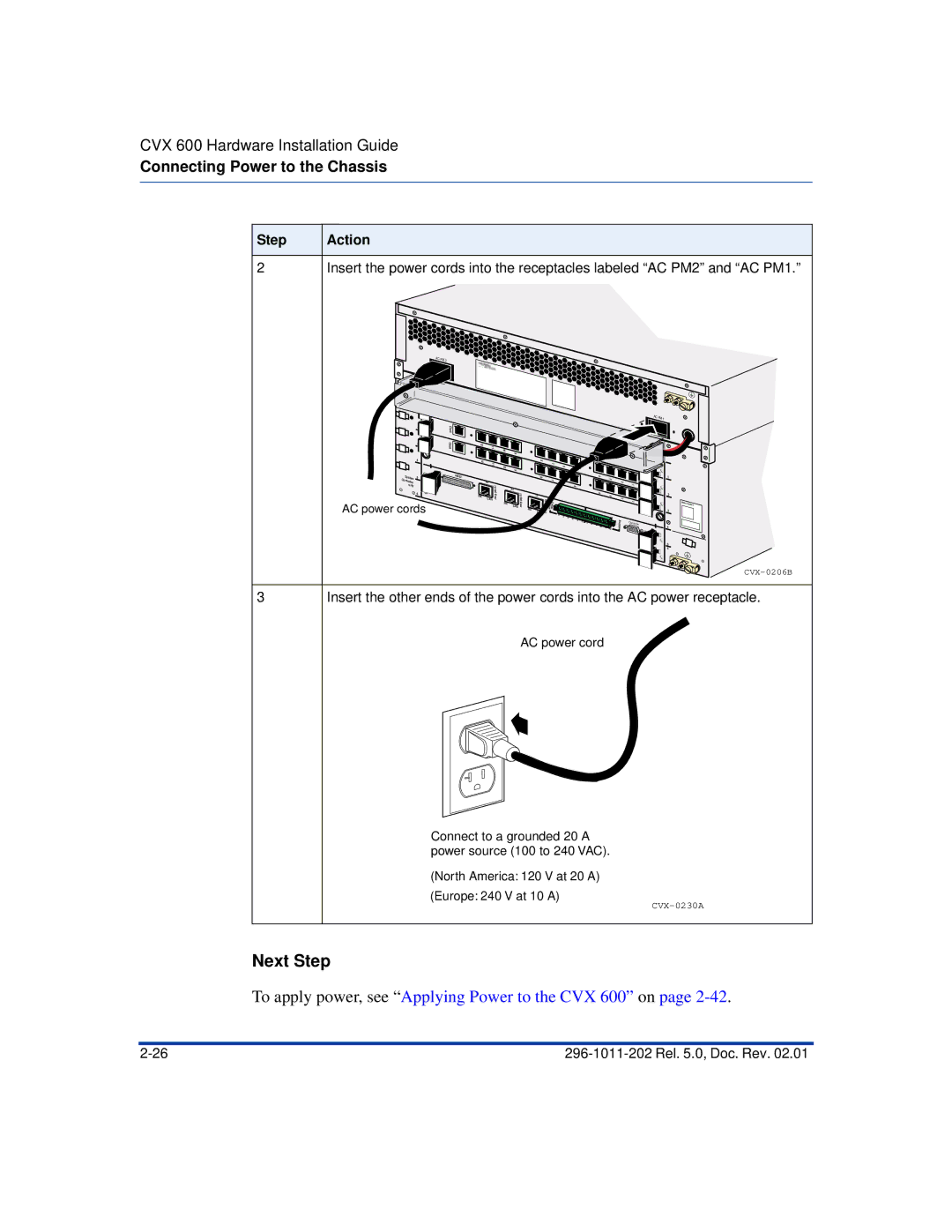
Connecting Power to the Chassis
Requirements
Grounding the Chassis
Use the compression terminal
Using the NEBS-Compliant Dual-Connector Posts
Using the Compression Terminal
Use a flat-tip screwdriver to loosen the locking screw
Connecting to a Customer-Supplied DC Power Source
Prerequisites
Remove the nuts from the posts using a 3/8-inch nutdriver
Black cable to Return
Next Step
Tighten screws to 6 in-lb
AC power source is only for the AC chassis option
Connecting Chassis to an AC Power Source
Connecting the Power Cords
AC power cords
Next Step
Suggested Use
Routing the Cables
Cable Mounts
Locations of Cable Mounts
Minimum Radius
Routing Fiber Optic Cables
Introduction
Rack Standoff Brackets
Installing and Removing the Flash Memory Cards
Inserting a Flash Memory Card
To insert a flash memory card, follow these steps
Removing a Flash Memory Card
To remove a flash memory card, follow these steps
Connecting Equipment to the Console Port
Connecting a Terminal
Parameter Value
DB-9 to DB-9 console cable DB-9 port On terminal
Connecting a PC
DB-9 port on PC DB-9 to DB-9 console cable
Connecting a Modem
Modem Parameter Value/State
Modem AT or Hayes compatible
Connecting a Terminal Server
Sample Hardware Arrangement for CVX Switches
Rear Connections for Sample Hardware Arrangement
Recommendations
Connecting Equipment to a Local Ethernet Port
Connecting a Remote Device Using an Ethernet Port
Applying Power to the CVX
To apply power to the CVX 600, follow these steps
Checking the LEDs
SCC-HSSI-SM, SCC-HSSI-RLTM
SCC-SM, SCC-RLTM Ethernet 10/100 Mb/s ports
Following figure shows the LEDs on the SCC-SM and SCC-RLTM
LEDs on the SCC-RLTM
LEDs on the SCC-SM
Following table describes the LEDs on the SCC-SM
Following table describes the LEDs on the SCC-RLTM
SCC-HSSI-SM, SCC-HSSI-RLTM
LEDs on the SCC-HSSI-RLTM
LEDs on the SCC-HSSI-SM
Following table describes the LEDs on the SCC-HSSI-SM
Following table describes the LEDs on the SCC-HSSI-RLTM
Optical SCC-II
SCC-II-LTM
LEDs on the Optical SCC-II-SM
Following table describes the LEDs on the Optical SCC-II-SM
LEDs on the Optical SCC-II-LTM
Following table describes the LEDs on the Optical SCC-II-LTM
LEDs on the Optical DAC-SM
Optical DAC
Following figure shows the LEDs on the Optical DAC-SM
Following table describes the LEDs on the Optical DAC-SM
DAC-SM LEDs
LEDs on DAC-SM
LEDs on the MAC-SM
MAC-SM LEDs
Following figure shows the LEDs on the MAC-SM
Following table describes the LEDs on the MAC-SM
Replacing CVX 600 Components
Location of Wrist Strap
How to Attach the Wrist Strap
Attaching the Antistatic Wrist Strap
Purpose of Wrist Strap
Replacing CVX 600 Components
Removing and Installing Filler Panels
Replacing Modules and Filler Panels
Removing a Rear Filler Panel
To remove a rear filler panel, follow these steps
To install a rear filler panel, follow these steps
Replacing Modules and Filler Panels
Removing a Front Filler Panel
To remove a front filler panel, follow these steps
Installing a Front Filler Panel
To install a front filler panel, follow these steps
Ejector At an
Close ejectors
Replacing the SCC-SM
Removing the SCC-SM
To remove the SCC-SM, follow these steps
CVX-0150C
Installing an SCC-SM
To install an SCC-SM, follow these steps
Close ejector levers
Removing the SCC-LTM or SCC-RLTM
Replacing the SCC-LTM/RLTM
To remove the SCC-LTM or SCC-RLTM, follow these steps
CVX-0154B
CVX-0155B
Installing an SCC-LTM or SCC-RLTM
To install an SCC-LTM or SCC-RLTM, follow these steps
CVX-0157C
Replacing Other Service Modules
Replacement Procedure
Removing a Service Module
To remove a MAC or DAC-SM, follow these steps
CVX-0159B
Installing a Service Module
To install a MAC or DAC-SM, follow these steps
For information about the LEDs, see Checking the LEDs on
Replacing the DAC-LTM/-RLTM
References
Removing a DAC-LTM or DAC-RLTM
To remove a DAC-LTM or DAC-RLTM, follow these steps
CVX-0163C
Installing a DAC-LTM or DAC-RLTM
CVX-0165B
Replacing the Fan Module
Removing the Fan Module
To remove the fan module, follow these steps
CVX-0167B
Installing a Fan Module
To install a fan module, follow these steps
CVX-0169B
Removing the PDU Module
Replacing a PDU Module
To remove the PDU module, follow these steps
CVX-0171B
Installing a PDU Module
To install a PDU module, follow these steps
Locked Unlocked
Removing the Power Module
Replacing a Power Module
To remove a power module, follow these steps
CVX-0215B
Installing a Power Module
To install a power module, follow these steps
Verify that the LED is on Rel .0, Doc. Rev
Ordering Replacement Components
How to Order
About This Appendix
This appendix covers the following topics
Clearance
Chassis Specifications and Clearances
Dimensions, Weight, Slot Capacity
Attribute Measurement
Environmental Specifications
Specifications
Methods of Cooling
Cooling Requirements
Need for Ventilation
Airflow
Electromagnetic Emissions and Radio Frequency
CVX 600 Requirements
Cables Supplied by Nortel Networks
Cable Specifications
Cables Supplied by the Customer
DB-9 Pin and Signal Assignments
Management Console Cable Specifications
Pin Signal To Signal
DB-9 to DB-25 Pin and Signal Assignments
Pin on DB-9 Connector Signal Name Pin on DB-25 Connector
Nortel Networks Termination Remote Termination Pin Signal
Following figure shows the Hssi connector
Hssi DTE to DCE Pin and Signal Assignments
Hssi Interface
Cable Specifications
Ethernet 10/100BASE-TX Pin and Signal Assignments
Ethernet 10/100BASE-TX Interface Cable Specifications
Pin Standard Interface Signal Crossover
RJ-45 Pin and Signal Assignments
E1 and T1 Interface Line Specifications
Pin Standard Interface Signal E1, T1 Signal
DS3 Coaxial Cable Specifications
E1 and T1 Shielded Cable Specifications
Optical Cable Specifications
Pin Data
Tandem CVX to RAS CVX Crossover Cable
Tool and Parts Needed
From
Following figure shows the numbering of the RJ-45 connector
RJ-45 Pin Numbering
Signals
Audible and Visual Alarm Interface Specifications
Alarm Interface Connector
Position Audible Signal Visual Signal
AC Power Requirements
Power Specifications
Power Options
DC Power Requirements
SCC-LTM/-RLTM Interfaces
Interface Description
DAC-LTM/-RLTM External Clock Interface
Page
Index
Index-2
Rel .0, Doc. Rev Index-3
Page
Page
CVX 600 Multi-Service Access Switch