CONTROLS AND THEIR FUNCTIONS
y 2 3 r 5 6 2 4 t 5 6 | w e |
|
| VIDEO IN |
| EDL |
|
| V | PB |
DC IN | T VIDEO/Y | |
R |
| |
1 | 2 | VIDEO OUT |
| ||
|
| |
| CH 1 | AUDIO IN |
| CH 2 | |
| V |
|
| T |
|
| R | AUDIO OUT |
| 2 CH 1 | CH 2 |
PR
REMOTE
VIDEO MON /TC OUT
MIC
LINE
AUDIO MON OUT
| VIDEO IN | REMOTE |
VIDEO/Y | PB | PR |
| PB VIDEO OUT | VIDEO MON /TC OUT |
| CH 1 | AUDIO IN |
| CH 2 | |
AUDIO MON OUT | AUDIO OUT | |
| CH 1 | CH 2 |
VREF ![]()
![]() TC IN T THROUGH
TC IN T THROUGH ![]()
R
1
REF IN 75ΩAUTO
V T R 1
7 | 9 8 q q 7 0 |
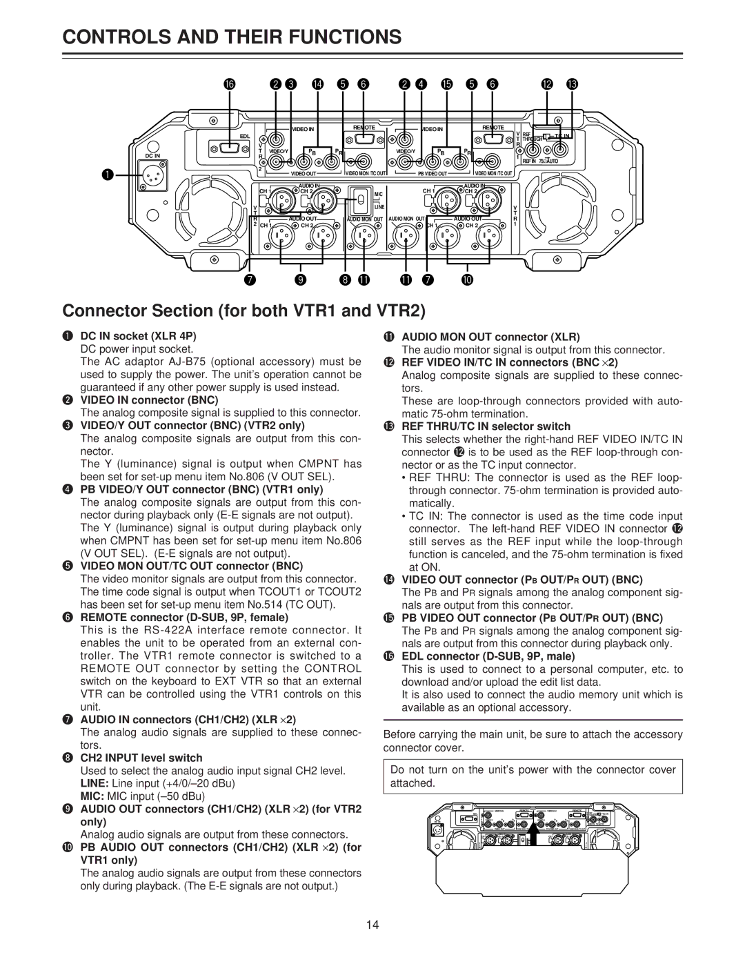
Connector Section (for both VTR1 and VTR2)
qDC IN socket (XLR 4P) DC power input socket.
The AC adaptor
wVIDEO IN connector (BNC)
The analog composite signal is supplied to this connector.
eVIDEO/Y OUT connector (BNC) (VTR2 only)
The analog composite signals are output from this con- nector.
The Y (luminance) signal is output when CMPNT has been set for
rPB VIDEO/Y OUT connector (BNC) (VTR1 only)
The analog composite signals are output from this con- nector during playback only
The Y (luminance) signal is output during playback only when CMPNT has been set for
tVIDEO MON OUT/TC OUT connector (BNC)
The video monitor signals are output from this connector. The time code signal is output when TCOUT1 or TCOUT2 has been set for
yREMOTE connector (D-SUB, 9P, female)
This is the
unit.
uAUDIO IN connectors (CH1/CH2) (XLR ⋅2)
The analog audio signals are supplied to these connec-
tors.
iCH2 INPUT level switch
Used to select the analog audio input signal CH2 level. LINE: Line input
MIC: MIC input
oAUDIO OUT connectors (CH1/CH2) (XLR ⋅2) (for VTR2
only)
Analog audio signals are output from these connectors.
!0PB AUDIO OUT connectors (CH1/CH2) (XLR ⋅2) (for
VTR1 only)
The analog audio signals are output from these connectors only during playback. (The
!1AUDIO MON OUT connector (XLR)
The audio monitor signal is output from this connector. !2REF VIDEO IN/TC IN connectors (BNC ⋅2)
Analog composite signals are supplied to these connec- tors.
These are
!3REF THRU/TC IN selector switch
This selects whether the
•REF THRU: The connector is used as the REF loop- through connector.
•TC IN: The connector is used as the time code input connector. The
function is canceled, and the
!4VIDEO OUT connector (PB OUT/PR OUT) (BNC)
The PB and PR signals among the analog component sig- nals are output from this connector.
!5PB VIDEO OUT connector (PB OUT/PR OUT) (BNC) The PB and PR signals among the analog component sig- nals are output from this connector during playback only.
!6EDL connector
This is used to connect to a personal computer, etc. to download and/or upload the edit list data.
It is also used to connect the audio memory unit which is available as an optional accessory.
Before carrying the main unit, be sure to attach the accessory connector cover.
Do not turn on the unit’s power with the connector cover attached.
|
| VIDEO IN | REMOTE |
| VIDEO IN | REMOTE | V REF |
|
| EDL |
|
|
|
|
| TC IN | |
|
|
|
|
|
| T THROUGH | ||
| V | PB | PR |
| PB | PR | R |
|
DC IN | T VIDEO/Y | VIDEO/Y | 1 |
| ||||
R |
|
|
|
|
|
| ||
|
|
|
|
|
|
| REF IN 75ΩAUTO | |
| 2 | VIDEO OUT | VIDEO MON /TC |
| PB VIDEO OUT | VIDEO MON /TC OUT |
|
|
|
|
|
|
| ||||
| CH 1 | AUDIO IN |
|
| CH 1 | AUDIO IN |
|
|
| CH 2 | MIC |
| CH 2 |
|
| ||
| V |
| LINE |
|
|
| V |
|
| T |
|
|
|
|
| T |
|
| R | AUDIO OUT | AUDIO MON OUT | AUDIO MON OUT | AUDIO OUT | R |
| |
| 2 CH 1 | CH 2 |
|
| CH 1 | CH 2 | 1 |
|
14