MAJOR OPERATING CONTROLS AND THEIR FUNCTIONS
q w e
WV
r
u
i t
yo
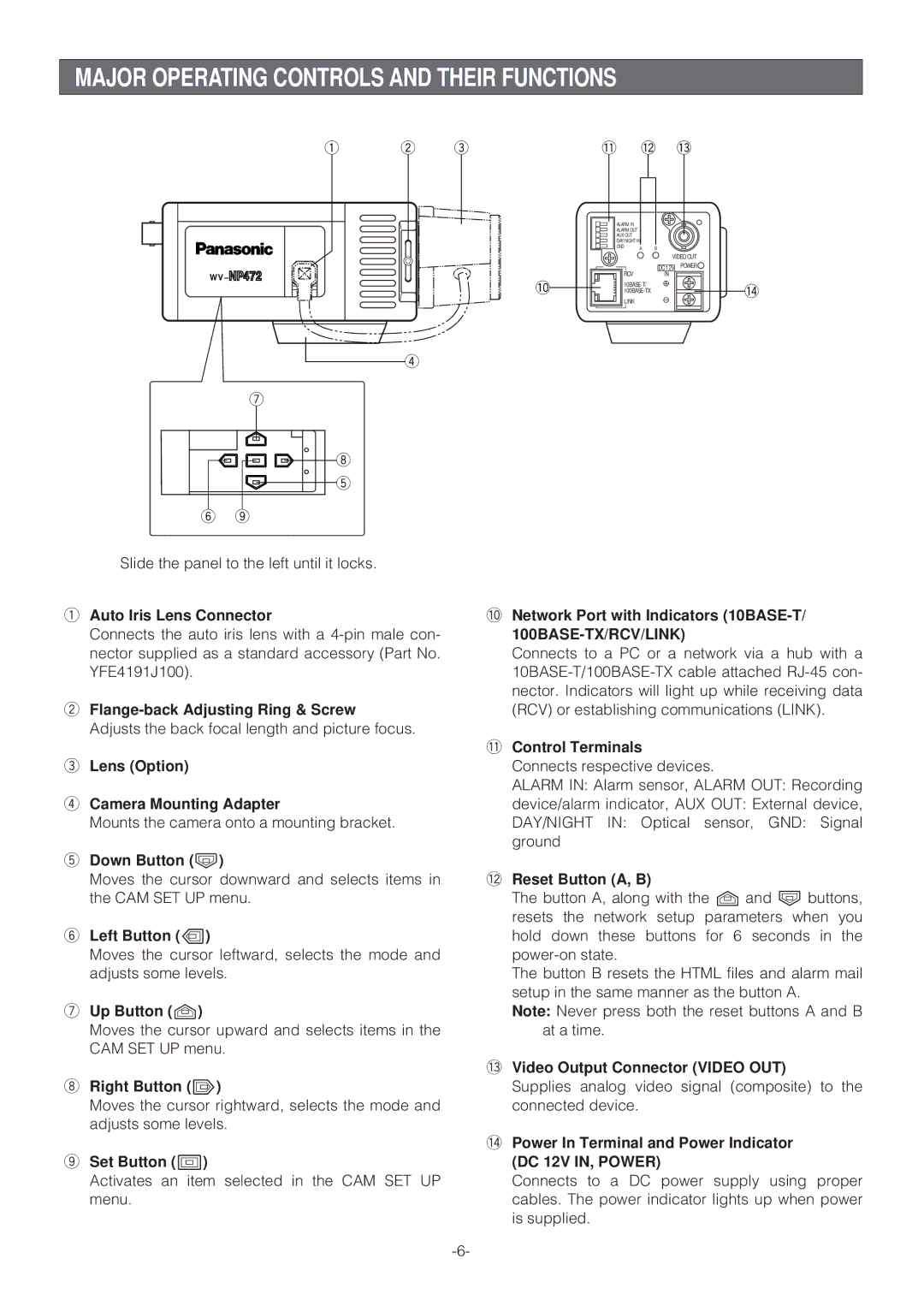
Slide the panel to the left until it locks.
qAuto Iris Lens Connector
Connects the auto iris lens with a
w
Adjusts the back focal length and picture focus.
eLens (Option)
rCamera Mounting Adapter
Mounts the camera onto a mounting bracket.
tDown Button (K)
Moves the cursor downward and selects items in the CAM SET UP menu.
yLeft Button (L)
Moves the cursor leftward, selects the mode and adjusts some levels.
uUp Button (J)
Moves the cursor upward and selects items in the CAM SET UP menu.
i Right Button (M)
Moves the cursor rightward, selects the mode and adjusts some levels.
oSet Button (I)
Activates an item selected in the CAM SET UP menu.
| !1 | !2 | !3 | |
| ALARM IN |
|
|
|
| ALARM OUT |
|
|
|
| AUX OUT |
|
|
|
| DAY/NIGHT IN |
|
| |
| GND | A | B |
|
|
|
| VIDEO OUT | |
| RCV |
| DC 12V | POWER |
|
| IN |
| |
!0 |
| !4 | ||
| ||||
| LINK |
|
|
|
!0Network Port with Indicators (10BASE-T/ 100BASE-TX/RCV/LINK)
Connects to a PC or a network via a hub with a
!1Control Terminals
Connects respective devices.
ALARM IN: Alarm sensor, ALARM OUT: Recording
device/alarm indicator, AUX OUT: External device,
DAY/NIGHT IN: Optical sensor, GND: Signal ground
!2Reset Button (A, B)
The button A, along with the J and K buttons, resets the network setup parameters when you hold down these buttons for 6 seconds in the
The button B resets the HTML files and alarm mail setup in the same manner as the button A.
Note: Never press both the reset buttons A and B at a time.
!3Video Output Connector (VIDEO OUT)
Supplies analog video signal (composite) to the connected device.
!4Power In Terminal and Power Indicator (DC 12V IN, POWER)
Connects to a DC power supply using proper cables. The power indicator lights up when power is supplied.
