CONNECTIONS
Power-in Connections
Notes:
•Use only a
•Use a UL listed cable
You can use the formula below to select the power supply, and power cable. The supplied voltage to the
10.8V(minimum) ≤ VA – 2RLI ≤ 16V (maximum)
VA: Output voltage of power supply
R:Resistance (Ω /m) (Ω /ft), see table
L:Cable length (m) (ft)
I:Consumption current (A), see specifications
Resistance of copper wire [at 20 °C (68 °F)]
Copper wire | #24 | #22 | #20 | #18 |
size (AWG) | (0.22 mm2) | (0.33 mm2) | (0.52 mm2) | (0.83 mm2) |
|
|
|
|
|
Resistance | 0.078 | 0.050 | 0.030 | 0.018 |
Ω /m |
|
|
|
|
|
|
|
|
|
Resistance | 0.026 | 0.017 | 0.010 | 0.006 |
Ω /ft |
|
|
|
|
|
|
|
|
|
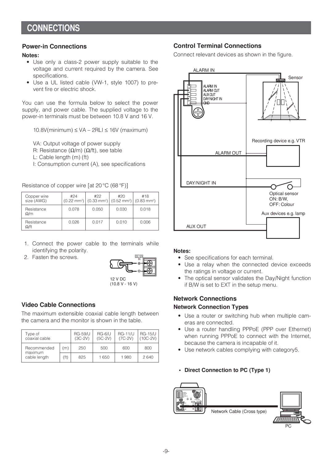
Control Terminal Connections
Connect relevant devices as shown in the figure.
ALARM IN
Sensor |
ALARM IN |
ALARM OUT |
AUX OUT |
DAY/NIGHT IN |
GND |
Recording device e.g. VTR |
ALARM OUT |
DAY/NIGHT IN |
Optical sensor |
ON: B/W, |
OFF: Colour |
Aux devices e.g. lamp |
AUX OUT
1. Connect the power cable to the terminals while
identifying the polarity. |
|
|
|
|
|
2. Fasten the screws. |
|
|
|
| |
|
| IN |
| ||
|
| DC 12V |
| ||
|
|
|
|
|
|
|
|
|
|
|
|
12 V DC
(10.8 V - 16 V)
Video Cable Connections
The maximum extensible coaxial cable length between the camera and the monitor is shown in the table.
Type of |
| ||||
coaxial cable |
| ||||
|
|
|
|
|
|
Recommended | (m) | 250 | 500 | 600 | 800 |
maximum |
|
|
|
|
|
|
|
|
|
| |
cable length | (ft) | 825 | 1 650 | 1 980 | 2 640 |
|
|
|
|
|
|
Notes:
•See specifications for each terminal.
•Use a relay when the connected device exceeds the ratings in voltage or current.
•The optical sensor validates the Day/Night function if B/W is set to EXT in the setup menu.
Network Connections
Network Connection Types
•Use a router or switching hub when multiple cam- eras are connected.
•Use a router handling PPPoE (PPP over Ethernet) when running PPPoE to connect with the Internet, because the camera is incapable of it.
•Use network cables complying with category5.
•Direct Connection to PC (Type 1)
ALARM IN
ALARM OUT
AUX OUT
DAY/NIGHT IN
GND A B
VIDEO OUT
DC 12V POWER
RCVIN
LINK
Network Cable (Cross type)
PC