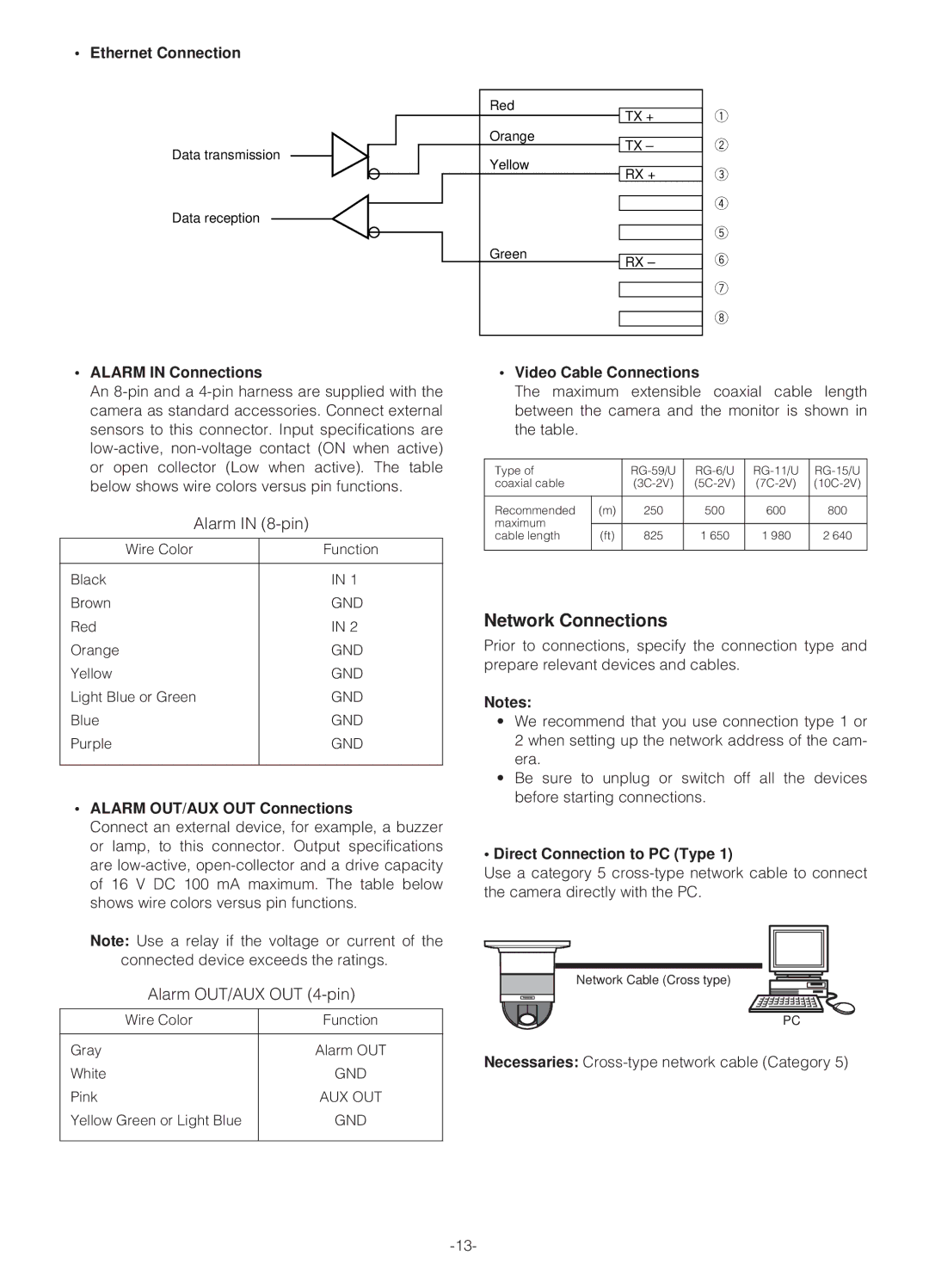
• Ethernet Connection
Data transmission
Data reception
Red
Orange
Yellow
Green
TX +
TX –
RX +
RX –
q
w
e
r
t
y
u
i
•ALARM IN Connections
An
Alarm IN |
| |
Wire Color |
| Function |
|
|
|
Black |
| IN 1 |
Brown |
| GND |
Red |
| IN 2 |
Orange |
| GND |
Yellow |
| GND |
Light Blue or Green |
| GND |
Blue |
| GND |
Purple |
| GND |
|
|
|
•ALARM OUT/AUX OUT Connections
Connect an external device, for example, a buzzer or lamp, to this connector. Output specifications are
Note: Use a relay if the voltage or current of the connected device exceeds the ratings.
Alarm OUT/AUX OUT (4-pin)
Wire Color | Function |
|
|
Gray | Alarm OUT |
White | GND |
Pink | AUX OUT |
Yellow Green or Light Blue | GND |
|
|
•Video Cable Connections
The maximum extensible coaxial cable length between the camera and the monitor is shown in the table.
Type of |
| ||||
coaxial cable |
| ||||
|
|
|
|
|
|
Recommended | (m) | 250 | 500 | 600 | 800 |
maximum |
|
|
|
|
|
|
|
|
|
| |
cable length | (ft) | 825 | 1 650 | 1 980 | 2 640 |
|
|
|
|
|
|
Network Connections
Prior to connections, specify the connection type and prepare relevant devices and cables.
Notes:
•We recommend that you use connection type 1 or 2 when setting up the network address of the cam- era.
•Be sure to unplug or switch off all the devices before starting connections.
•Direct Connection to PC (Type 1)
Use a category 5
Network Cable (Cross type)
PC
Necessaries: