INSTALLATION
Precautions
•The following installation and connection work should be done by qualified service personnel or system installers and should conform to all local codes.
•Be sure to switch the camera off before installation and connection.
•Do not install the camera near the air outlet of an air conditioner.
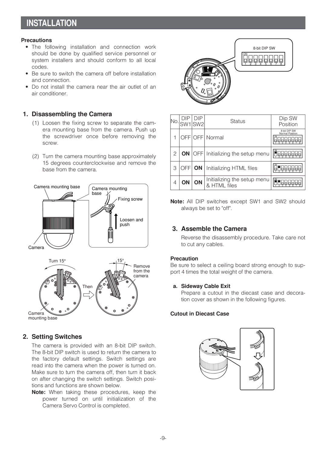
1.Disassembling the Camera
(1)Loosen the fixing screw to separate the cam- era mounting base from the camera. Push up the screwdriver once before removing the screw.
(2)Turn the camera mounting base approximately 15 degrees counterclockwise and remove the base from the camera.
Camera mounting base | Camera mounting |
| |
| base |
![]() Fixing screw
Fixing screw
Loosen and push
Camera
Turn 15° | 15° |
Remove from the camera
Then
Camera mounting base
2. Setting Switches
The camera is provided with an
Note: When taking these procedures, keep the power turned on until initialization of the Camera Servo Control is completed.
ON
1 2 3 4 5 6 7 8
No. | DIP | DIP | Status |
|
| Dip SW |
|
| |||||
SW1 | SW2 |
|
| Position |
|
| |||||||
|
|
|
|
|
|
|
|
|
|
| |||
|
|
|
|
|
|
|
|
|
| ||||
1 | OFF | OFF | Normal |
|
| Normal Position |
|
| |||||
| ON |
|
|
|
|
|
|
|
| ||||
|
|
|
|
| 1 | 2 | 3 | 4 | 5 | 6 | 7 | 8 |
|
|
|
|
|
|
|
|
|
|
|
|
|
|
|
|
|
|
|
|
|
|
|
|
|
|
|
|
|
2 | ON | OFF | Initializing the setup menu |
| ON |
|
|
|
|
|
|
|
|
| 1 | 2 | 3 | 4 | 5 | 6 | 7 | 8 |
| ||||
|
|
|
|
|
| ||||||||
|
|
|
|
|
|
|
|
|
|
|
|
|
|
|
|
|
|
|
|
|
|
|
|
|
|
|
|
3 | OFF | ON | Initializing HTML files |
| ON |
|
|
|
|
|
|
|
|
| 1 | 2 | 3 | 4 | 5 | 6 | 7 | 8 |
| ||||
|
|
|
|
|
| ||||||||
|
|
|
|
|
|
|
|
|
|
|
|
|
|
|
|
| Initializing the setup menu |
|
|
|
|
|
|
|
|
|
|
4 | ON | ON | ON |
|
|
|
|
|
|
|
| ||
|
|
| & HTML files |
| 1 | 2 | 3 | 4 | 5 | 6 | 7 | 8 |
|
|
|
|
|
|
|
|
|
|
|
|
|
|
|
Note: All DIP switches except SW1 and SW2 should always be set to "off".
3. Assemble the Camera
Reverse the disassembly procedure. Take care not to cut any cables.
Precaution
Be sure to select a ceiling board strong enough to sup- port 4 times the total weight of the camera.
a.Sideway Cable Exit
Prepare a cutout in the diecast case and decora- tion cover as shown in the following figures.
Cutout in Diecast Case