Major Fibre Channel Port Features
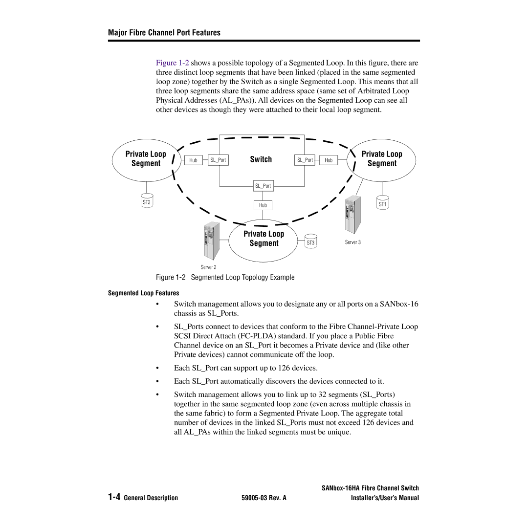
Figure 1-2 shows a possible topology of a Segmented Loop. In this figure, there are three distinct loop segments that have been linked (placed in the same segmented loop zone) together by the Switch as a single Segmented Loop. This means that all three loop segments share the same address space (same set of Arbitrated Loop Physical Addresses (AL_PAs)). All devices on the Segmented Loop can see all other devices as though they were attached to their local loop segment.
Private Loop
Segment
Hub ![]() SL_Port
SL_Port
Switch
SL_Port
SL_Port
Hub
Private Loop
Segment
ST2 | Hub | ST1 |
|
Private Loop
Segment | ST3 | Server 3 |
Server 2
Figure 1-2 Segmented Loop Topology Example
Segmented Loop Features
•Switch management allows you to designate any or all ports on a
•SL_Ports connect to devices that conform to the Fibre
•Each SL_Port can support up to 126 devices.
•Each SL_Port automatically discovers the devices connected to it.
•Switch management allows you to link up to 32 segments (SL_Ports) together in the same segmented loop zone (even across multiple chassis in the same fabric) to form a Segmented Private Loop. The aggregate total number of devices in the linked SL_Ports must not exceed 126 devices and all AL_PAs within the linked segments must be unique
| ||
| Installer’s/User’s Manual |