Cable Fibre Channel Devices to the Switch
Private Translated Loop Connections
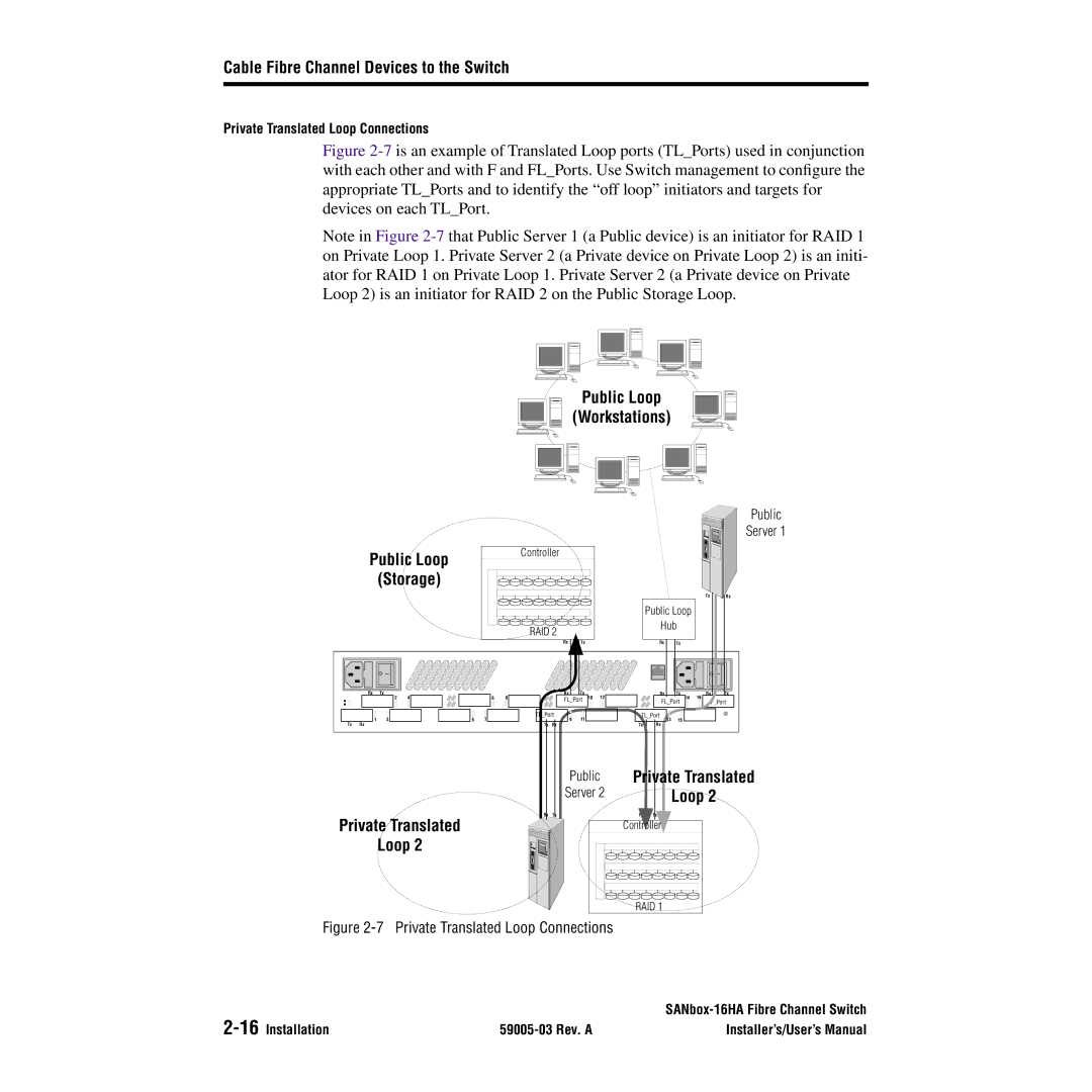
Figure 2-7 is an example of Translated Loop ports (TL_Ports) used in conjunction with each other and with F and FL_Ports. Use Switch management to configure the appropriate TL_Ports and to identify the “off loop” initiators and targets for devices on each TL_Port.
Note in Figure
Public Loop
(Workstations)
Public
Server 1
Public Loop | Controller |
| |
(Storage) |
|
Tx Rx
Public Loop
|
|
|
|
|
| RAID 2 |
|
|
|
| Hub |
|
| ||
|
|
|
|
|
|
|
|
|
|
|
|
|
| ||
|
|
|
|
|
|
| Rx |
| Tx |
|
| Rx | Tx |
|
|
| Rx | Tx |
|
|
|
| Rx |
| Tx |
|
| Rx | Tx | Rx | Tx |
|
| 2 | 4 |
| 6 | 8 | FL_Port | 10 | 12 |
| 14 | 16 | F_Port | ||
|
|
|
|
|
|
|
|
|
|
|
| FL_Port |
| ||
| 1 | 3 |
| 5 | 7 | TL_Port | 9 | 11 |
|
| TL_Port | 15 |
|
| |
|
|
|
|
|
| 13 |
|
| |||||||
Tx | Rx |
|
|
|
| Tx | Rx |
|
|
|
| Tx |
|
|
|
Public | Private Translated |
Server 2 | Loop 2 |
Private Translated
Loop 2
Rx Tx | Rx | Tx |
Controller![]()
RAID 1
Figure 2-7 Private Translated Loop Connections
| ||
| Installer’s/User’s Manual |
