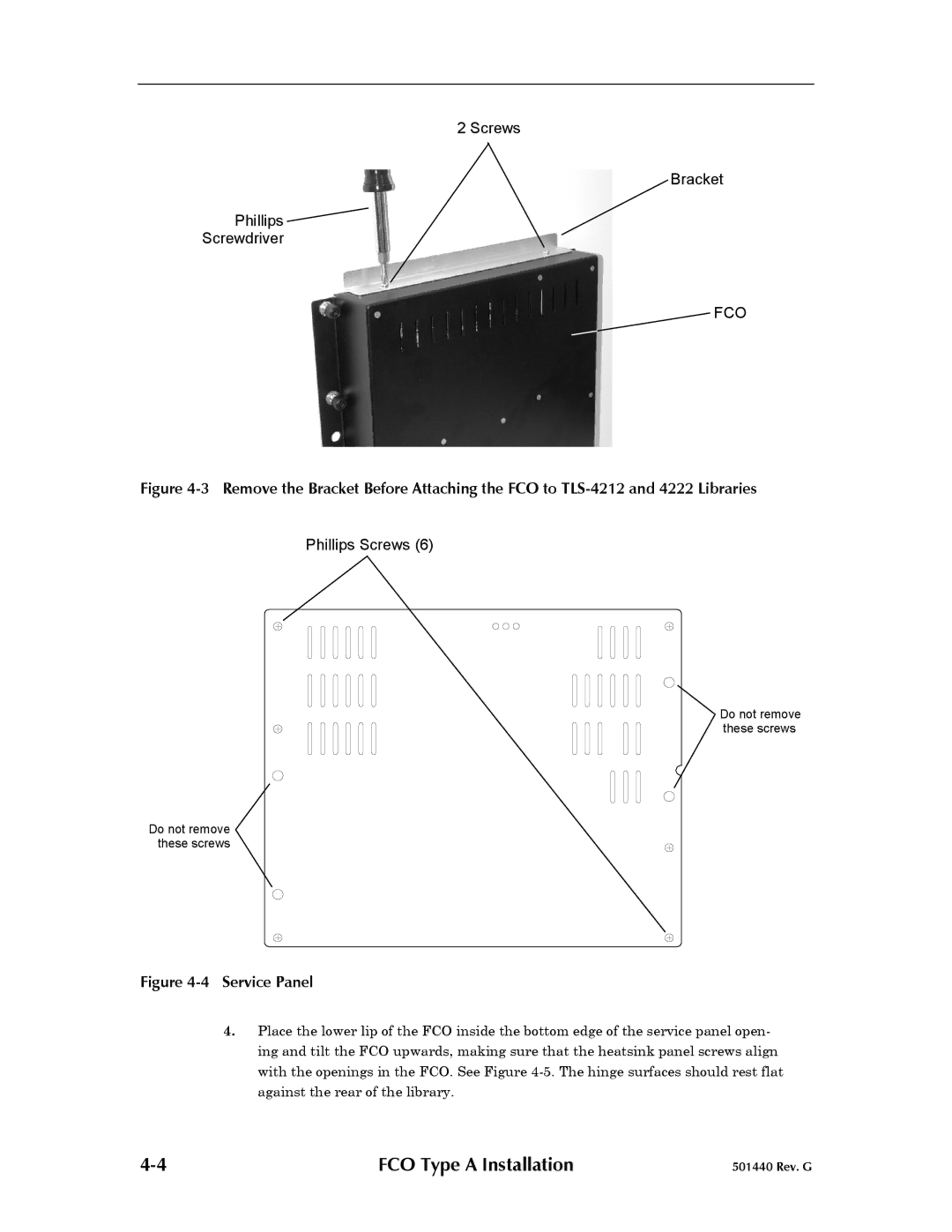
2 Screws
Bracket
Phillips ![]()
Screwdriver
FCO
Figure 4-3 Remove the Bracket Before Attaching the FCO to TLS-4212 and 4222 Libraries
Phillips Screws (6)
Do not remove these screws
Do not remove these screws
Figure 4-4 Service Panel
4.Place the lower lip of the FCO inside the bottom edge of the service panel open- ing and tilt the FCO upwards, making sure that the heatsink panel screws align with the openings in the FCO. See Figure
FCO Type A Installation | 501440 Rev. G |
