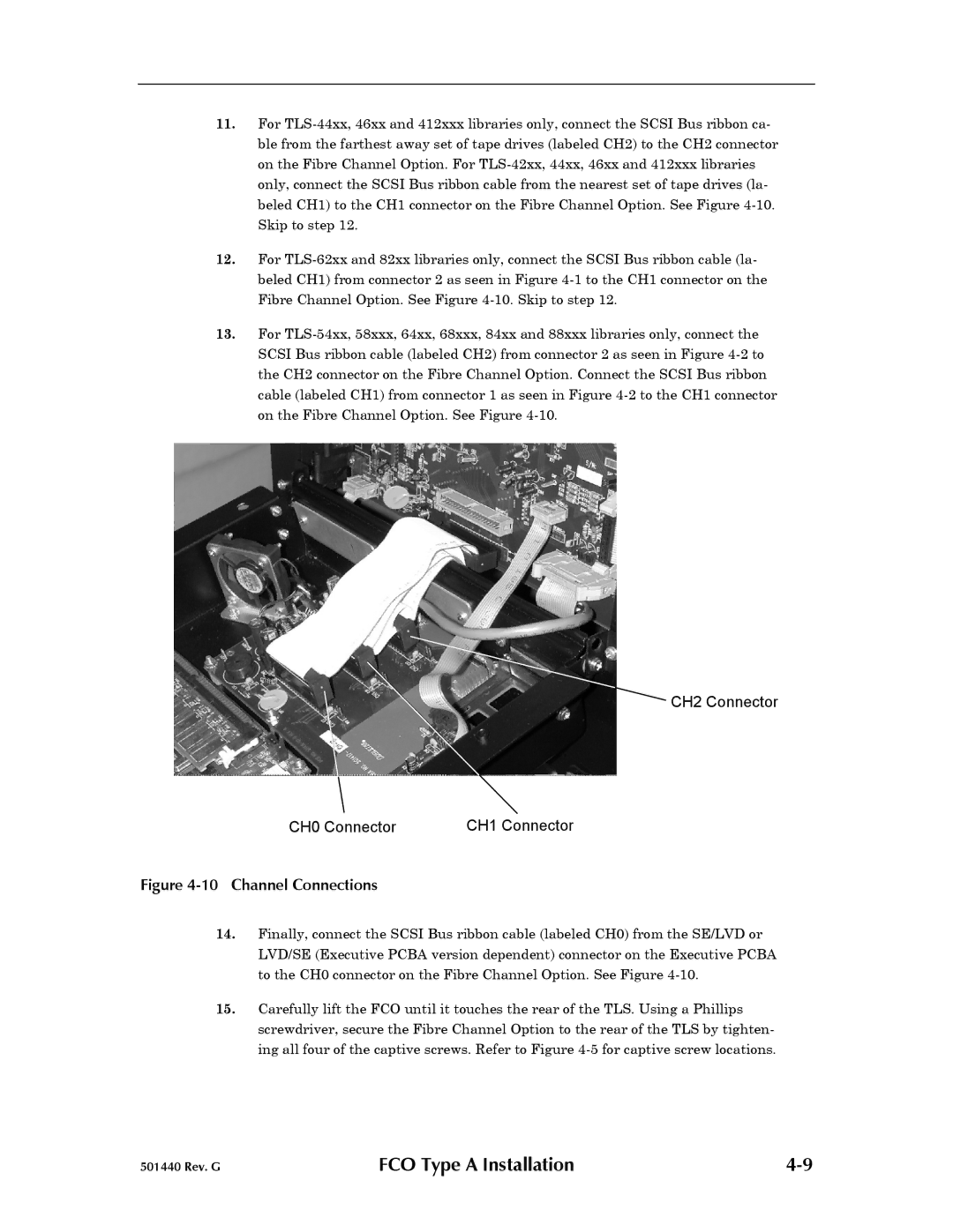
11.For TLS-44xx, 46xx and 412xxx libraries only, connect the SCSI Bus ribbon ca- ble from the farthest away set of tape drives (labeled CH2) to the CH2 connector on the Fibre Channel Option. For TLS-42xx, 44xx, 46xx and 412xxx libraries only, connect the SCSI Bus ribbon cable from the nearest set of tape drives (la- beled CH1) to the CH1 connector on the Fibre Channel Option. See Figure 4-10.Skip to step 12.
12.For TLS-62xx and 82xx libraries only, connect the SCSI Bus ribbon cable (la- beled CH1) from connector 2 as seen in Figure 4-1to the CH1 connector on the Fibre Channel Option. See Figure 4-10.Skip to step 12.
13.For TLS-54xx, 58xxx, 64xx, 68xxx, 84xx and 88xxx libraries only, connect the SCSI Bus ribbon cable (labeled CH2) from connector 2 as seen in Figure 4-2to the CH2 connector on the Fibre Channel Option. Connect the SCSI Bus ribbon cable (labeled CH1) from connector 1 as seen in Figure 4-2to the CH1 connector on the Fibre Channel Option. See Figure 4-10.
CH2 Connector
CH0 Connector | CH1 Connector |
Figure 4-10 Channel Connections
14.Finally, connect the SCSI Bus ribbon cable (labeled CH0) from the SE/LVD or LVD/SE (Executive PCBA version dependent) connector on the Executive PCBA to the CH0 connector on the Fibre Channel Option. See Figure 4-10.
15.Carefully lift the FCO until it touches the rear of the TLS. Using a Phillips screwdriver, secure the Fibre Channel Option to the rear of the TLS by tighten- ing all four of the captive screws. Refer to Figure 4-5for captive screw locations.
501440 Rev. G | FCO Type A Installation | 4-9 |

