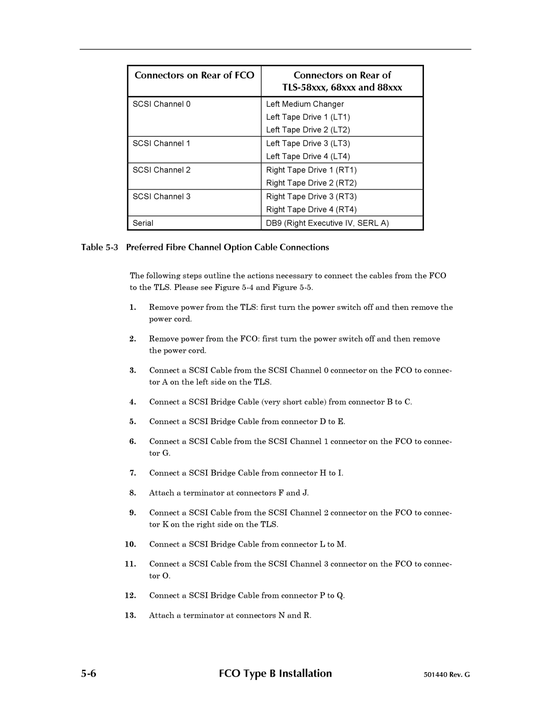
Connectors on Rear of FCO | Connectors on Rear of |
|
|
|
|
SCSI Channel 0 | Left Medium Changer |
| Left Tape Drive 1 (LT1) |
| Left Tape Drive 2 (LT2) |
|
|
SCSI Channel 1 | Left Tape Drive 3 (LT3) |
| Left Tape Drive 4 (LT4) |
|
|
SCSI Channel 2 | Right Tape Drive 1 (RT1) |
| Right Tape Drive 2 (RT2) |
SCSI Channel 3 | Right Tape Drive 3 (RT3) |
| Right Tape Drive 4 (RT4) |
Serial | DB9 (Right Executive IV, SERL A) |
|
|
Table 5-3 Preferred Fibre Channel Option Cable Connections
The following steps outline the actions necessary to connect the cables from the FCO to the TLS. Please see Figure
1.Remove power from the TLS: first turn the power switch off and then remove the power cord.
2.Remove power from the FCO: first turn the power switch off and then remove the power cord.
3.Connect a SCSI Cable from the SCSI Channel 0 connector on the FCO to connec- tor A on the left side on the TLS.
4.Connect a SCSI Bridge Cable (very short cable) from connector B to C.
5.Connect a SCSI Bridge Cable from connector D to E.
6.Connect a SCSI Cable from the SCSI Channel 1 connector on the FCO to connec- tor G.
7.Connect a SCSI Bridge Cable from connector H to I.
8.Attach a terminator at connectors F and J.
9.Connect a SCSI Cable from the SCSI Channel 2 connector on the FCO to connec- tor K on the right side on the TLS.
10.Connect a SCSI Bridge Cable from connector L to M.
11.Connect a SCSI Cable from the SCSI Channel 3 connector on the FCO to connec- tor O.
12.Connect a SCSI Bridge Cable from connector P to Q.
13.Attach a terminator at connectors N and R.
FCO Type B Installation | 501440 Rev. G |